- 您現在的位置:買賣IC網 > PDF目錄98266 > TMDS461PZIT (TEXAS INSTRUMENTS INC) SPECIALTY CONSUMER CIRCUIT, PQFP100 PDF資料下載
參數資料
| 型號: | TMDS461PZIT |
| 廠商: | TEXAS INSTRUMENTS INC |
| 元件分類: | 消費家電 |
| 英文描述: | SPECIALTY CONSUMER CIRCUIT, PQFP100 |
| 封裝: | PLASTIC, TQFP-100 |
| 文件頁數: | 2/24頁 |
| 文件大小: | 1467K |
| 代理商: | TMDS461PZIT |
PRODUCTPREVIEW
DEVICE POWER
ELECTRICAL CHARACTERISTICS
HOT PLUG DETECT and 5V DETECT
SLLS915 – AUGUST 2008 ................................................................................................................................................................................................. www.ti.com
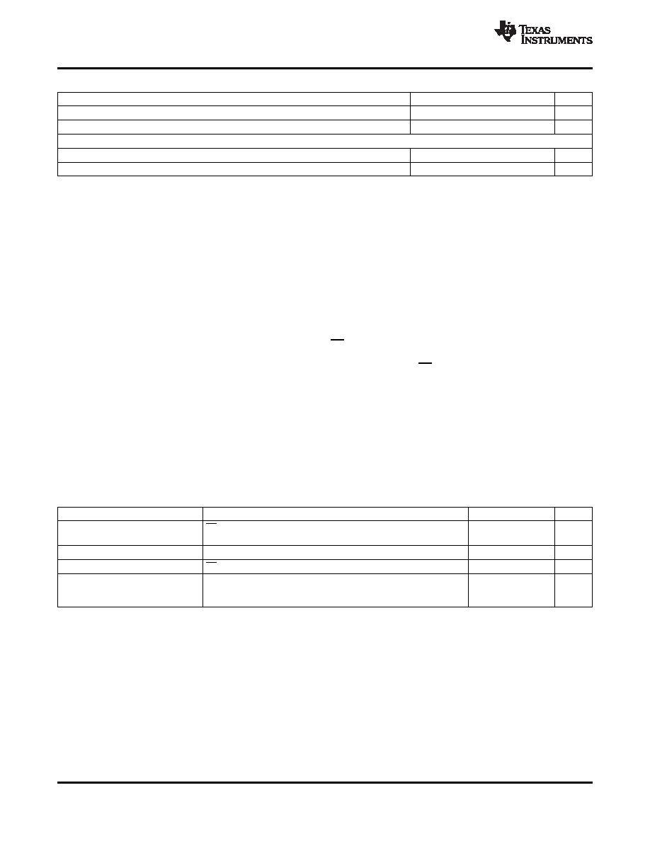
RECOMMENDED OPERATING CONDITIONS (continued)
MIN
NOM
MAX
UNIT
VI
Input voltage
0
5.5
V
dR(I2C)
I2C data rate
100
Kbps
HPD 5V_PWR, AND CONTROL PINS
VIH
High-level input voltage
2
5.5
V
VIL
Low-level input votlage
0
0.8
V
The TMDS461 is designed to operate from a single 3.3-V supply voltage. The TMDS461 has three power modes
of operation. These three modes are referred to as normal mode, standby mode, and low-power mode.
Normal mode is designed to be used during typical operating conditions. In normal mode, the device is fully
functional and consumes the greatest amount of power.
Standby mode is designed to be used when reduced power is desired, but DDC and HPD communication must
be maintained. Standby mode can be enabled via the I2C interface. In standby mode, the high-speed TMDS data
and clock channels are disabled to reduce power consumption. The internal I2C logic, DDC, and HPD function
normally.
Low-power mode is designed to consume the least possible amount of power while still applying the 3.3 V to the
device. Low-power mode can be enabled by either the LP GPIO pin (pin 85) or by an I2C command via the
internal I2C logic. In low power mode all of the inputs and output are disabled with the exception of the internal
I2C logic and I/O. Low-power mode can be disabled by either the either the LP GPIO pin (pin 85) in GPIO mode
or by an I2C command via the internal I2C logic in the I2C mode.
Clock Detection feature in TMDS461 provides an automatic power management feature in normal mode. If there
is no valid TMDS clock detected, the terminations on the input TMDS data lines are disconnected and the TMDS
outputs are Hi-Z. As soon as a valid TMDS clock is detected, the terminations on the input TMDS data lines are
connected and TMDS outputs come out of Hi-Z, the device is fully functional and consumes the greatest amount
of power.
over recommended operating conditions (unless otherwise noted)
PARAMETER
TEST CONDITIONS
MIN
TYP
MAX
UNIT
ICC
Supply current (normal
LP = 3.3 V, TMDS: VID = 500 mV, 3 Gbps PRBS, HPD = 3.3 V,
216
mA
mode)
5V_PWR[1:4] = 5 V
ISTBY
Standby supply current
5
mA
ISD
Shutdown current
LP = 0V
555
A
INCLK
Supply current (normal
18
mA
mode: No TMDS clock
detected)
The TMDS461 is designed to support the Hot Plug indication to the input ports. The state of the Hot Plug output
of the selected source follows the state of the Hot Plug input. The state of the Hot Plug outputs of the
non-selected ports can be configured to either follow the state of the ports 5V_PWR, or they can be configured to
be high impedance until selected.
When in standby power mode the HPD pin will operate just as it does in normal operational mode.
10
Copyright 2008, Texas Instruments Incorporated
Product Folder Link(s) :TMDS461
相關PDF資料 |
PDF描述 |
|---|---|
| TMDS461PZT | SPECIALTY CONSUMER CIRCUIT, PQFP100 |
| TMDS461PZTR | SPECIALTY CONSUMER CIRCUIT, PQFP100 |
| TMP431BDGKT | SPECIALTY ANALOG CIRCUIT, PDSO8 |
| TMP435ADGST | SPECIALTY ANALOG CIRCUIT, PDSO10 |
| TMS320AV100PBM | SPECIALTY CONSUMER CIRCUIT, PQFP120 |
相關代理商/技術參數 |
參數描述 |
|---|---|
| TMDS461PZT | 功能描述:視頻開關 IC 4 to 1 HDMI Switch RoHS:否 制造商:Texas Instruments 開關數量:4 開啟電阻(最大值):12 Ohms 傳播延遲時間: 開啟時間(最大值): 關閉時間(最大值): 最大工作溫度:+ 85 C 最小工作溫度:- 40 C 封裝 / 箱體:WQFN-42 封裝:Reel |
| TMDS461PZTR | 功能描述:視頻開關 IC 4 to 1 HDMI Switch RoHS:否 制造商:Texas Instruments 開關數量:4 開啟電阻(最大值):12 Ohms 傳播延遲時間: 開啟時間(最大值): 關閉時間(最大值): 最大工作溫度:+ 85 C 最小工作溫度:- 40 C 封裝 / 箱體:WQFN-42 封裝:Reel |
| TMDS570LS12HDK | 功能描述:TMS570LS Hercules? MCU 32-Bit ARM? Cortex?-R4F Embedded Evaluation Board 制造商:texas instruments 系列:Hercules? 零件狀態:有效 板類型:評估平臺 類型:MCU 32-位 核心處理器:ARM? Cortex?-R4F 操作系統:- 平臺:- 配套使用產品/相關產品:TMS570LS 安裝類型:固定 內容:板,電纜,配件 標準包裝:1 |
| TMDS570LS31HDK | 制造商:Texas Instruments 功能描述:HERCULES DEVELOPMENT KIT |
| TMDS570LS31USB | 功能描述:EVAL BOARD HERCULES 制造商:texas instruments 系列:Hercules? 零件狀態:停產 板類型:評估平臺 類型:MCU 32-位 核心處理器:ARM? Cortex?-R4F 操作系統:- 平臺:- 配套使用產品/相關產品:TMS570LS 安裝類型:固定 內容:板,電纜,配件 標準包裝:1 |
發布緊急采購,3分鐘左右您將得到回復。