- 您現在的位置:買賣IC網 > PDF目錄98266 > TMDS461PZTR (TEXAS INSTRUMENTS INC) SPECIALTY CONSUMER CIRCUIT, PQFP100 PDF資料下載
參數資料
| 型號: | TMDS461PZTR |
| 廠商: | TEXAS INSTRUMENTS INC |
| 元件分類: | 消費家電 |
| 英文描述: | SPECIALTY CONSUMER CIRCUIT, PQFP100 |
| 封裝: | PLASTIC, TQFP-100 |
| 文件頁數: | 32/43頁 |
| 文件大小: | 3111K |
| 代理商: | TMDS461PZTR |
第1頁第2頁第3頁第4頁第5頁第6頁第7頁第8頁第9頁第10頁第11頁第12頁第13頁第14頁第15頁第16頁第17頁第18頁第19頁第20頁第21頁第22頁第23頁第24頁第25頁第26頁第27頁第28頁第29頁第30頁第31頁當前第32頁第33頁第34頁第35頁第36頁第37頁第38頁第39頁第40頁第41頁第42頁第43頁
SLLS915 – JANUARY 2009 ............................................................................................................................................................................................... www.ti.com
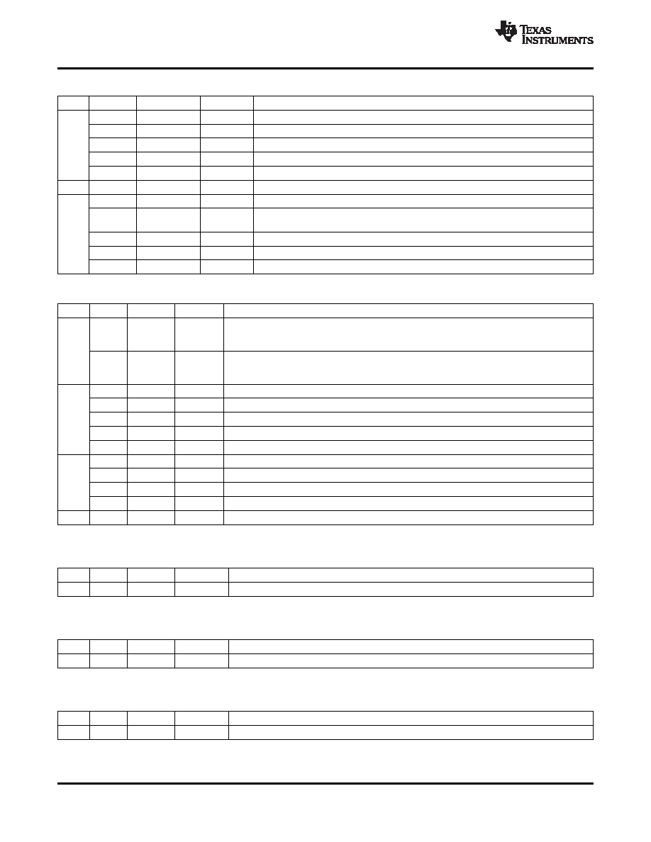
Table 8. I2C Register 0x02 Lookup Table (continued)
BIT
VALUE
STATE
DEFAULT
DESCRIPTION
4:3
Bit 4
Bit 3
Priority Select
0
X
Port 1 is the priority port
0
1
Port 2 is the priority port
1
0
Port 3 is the priority port
1
Port 4 is the priority port
2
0
Reserved
X
Reserved (Do not write a 1 to this bit)
1:0
Bit 1
Bit 0
Output Edge Rate Control
1
Fastest TMDS output rise and fall time setting + 120 ps approximately (slowest rise and
fall time setting)
1
0
Fastest TMDS output rise and fall time setting + 100 ps approximately
0
1
Fastest TMDS output rise and fall time setting + 50 ps approximately
0
X
Fastest TMDS output rise and fall time setting
Table 9. I2C Register 0x03 Lookup Table(1)
BIT
VALUE
STATE
DEFAULT
DESCRIPTION
7
0
Clock
X
Clock Detect Circuit Enabled. It is recommended that TMDS461 is used in this default mode in
Detect
the normal operation, where clock-detect circuit is enabled. The terminations on the TMDS input
Enabled
data lines are connected only when valid TMDS clock is detected on the selected port.
1
Clock
Clock Detect Circuit Disabled. For HDMI compliance testing (TMDS Termination Voltage Test),
Detect
clock-detect feature should be disabled. In this mode the terminations on the TMDS input data
Disabled
lines are always connected when the port is selected.
6:5
Bit 6
Bit 5
Port select I2C mode
0
X
Port 1 is selected as the active port, all other ports disabled.
0
1
Port 2 is selected as the active port, all other ports disabled.
1
0
Port 3 is selected as the active port, all other ports disabled.
1
Port 4 is selected as the active port, all other ports disabled.
4:3
Bit 4
Bit 3
OVS Control
0
DDC sink side VOL and VIL offset range 2: VIL2 (max) : 0.4V, VOL2 (max) : 0.6V
0
1
X
DDC sink side VOL and VIL offset range 3: VIL3 (max) : 0.3V, VOL3 (max) : 0.5V
1
DDC sink side VOL and VIL offset range 1: VIL1 (max) : 0.4V, VOL1 (max) : 0.7V
2:0
0
RSVD
X
Reserved
(1)
Register 0x03 is Read/Write.
Table 10. I2C Register 0x04 Lookup Table(1)
BIT
VALUE
STATE
DEFAULT
DESCRIPTION
7:0
—
RSVD
X
Reserved. Read-only, value is indeterministic.
(1)
Register x04 is TI internal usage only.
Table 11. I2C Register 0x05 Lookup Table(1)
BIT
VALUE
STATE
DEFAULT
DESCRIPTION
7:0
—
RSVD
X
Reserved. Read-only, value is indeterministic.
(1)
Register x05 is TI internal usage only.
Table 12. I2C Register 0x06 Lookup Table(1)
BIT
VALUE
STATE
DEFAULT
DESCRIPTION
7:0
—
RSVD
X
Reserved. Read-only, value is indeterministic.
(1)
Register x06 is TI internal usage only.
38
Copyright 2009, Texas Instruments Incorporated
Product Folder Link(s) :TMDS461
相關PDF資料 |
PDF描述 |
|---|---|
| TMP431BDGKT | SPECIALTY ANALOG CIRCUIT, PDSO8 |
| TMP435ADGST | SPECIALTY ANALOG CIRCUIT, PDSO10 |
| TMS320AV100PBM | SPECIALTY CONSUMER CIRCUIT, PQFP120 |
| TMS320AV120FN | SPECIALTY CONSUMER CIRCUIT, PQCC44 |
| TMS320AV220PCM | SPECIALTY CONSUMER CIRCUIT, PQFP144 |
相關代理商/技術參數 |
參數描述 |
|---|---|
| TMDS570LS12HDK | 功能描述:TMS570LS Hercules? MCU 32-Bit ARM? Cortex?-R4F Embedded Evaluation Board 制造商:texas instruments 系列:Hercules? 零件狀態:有效 板類型:評估平臺 類型:MCU 32-位 核心處理器:ARM? Cortex?-R4F 操作系統:- 平臺:- 配套使用產品/相關產品:TMS570LS 安裝類型:固定 內容:板,電纜,配件 標準包裝:1 |
| TMDS570LS31HDK | 制造商:Texas Instruments 功能描述:HERCULES DEVELOPMENT KIT |
| TMDS570LS31USB | 功能描述:EVAL BOARD HERCULES 制造商:texas instruments 系列:Hercules? 零件狀態:停產 板類型:評估平臺 類型:MCU 32-位 核心處理器:ARM? Cortex?-R4F 操作系統:- 平臺:- 配套使用產品/相關產品:TMS570LS 安裝類型:固定 內容:板,電纜,配件 標準包裝:1 |
| TMDS9P701014 | 制造商:Texas Instruments 功能描述: |
| TMDSACDCKIT | 功能描述:開發板和工具包 - TMS320 C2000 AC/DC Dev Kit RoHS:否 制造商:Texas Instruments 產品:Experimenter Kits 工具用于評估:F2802x 核心:TMS320 接口類型:UART, USB 工作電源電壓: |
發布緊急采購,3分鐘左右您將得到回復。