- 您現在的位置:買賣IC網 > PDF目錄98285 > TPS65171RHAR (TEXAS INSTRUMENTS INC) 4 A SWITCHED CAPACITOR REGULATOR, 900 kHz SWITCHING FREQ-MAX, PQCC40 PDF資料下載
參數資料
| 型號: | TPS65171RHAR |
| 廠商: | TEXAS INSTRUMENTS INC |
| 元件分類: | 穩壓器 |
| 英文描述: | 4 A SWITCHED CAPACITOR REGULATOR, 900 kHz SWITCHING FREQ-MAX, PQCC40 |
| 封裝: | 6 X 6 MM, GREEN, PLASTIC, MO-220VJJD-2, VQFN-40 |
| 文件頁數: | 17/46頁 |
| 文件大小: | 3644K |
| 代理商: | TPS65171RHAR |
第1頁第2頁第3頁第4頁第5頁第6頁第7頁第8頁第9頁第10頁第11頁第12頁第13頁第14頁第15頁第16頁當前第17頁第18頁第19頁第20頁第21頁第22頁第23頁第24頁第25頁第26頁第27頁第28頁第29頁第30頁第31頁第32頁第33頁第34頁第35頁第36頁第37頁第38頁第39頁第40頁第41頁第42頁第43頁第44頁第45頁第46頁
out
in
out
swpeak
in
swpeak
out
V
1. Converter Duty Cycle:
D =
V
(1
D)
2. Maximum output current: I
= I
D
2fs×L
V
(1 D)
3. Peak switch current:
I
= I
+
D
2fs
L
h
-
-
SLVSA22A – OCTOBER 2009 – REVISED JANUARY 2010
www.ti.com
Soft-Start (Buck Converter)
To avoid high inrush current during start-up, an internal soft-start is implemented. When the buck converter is
enabled, its current limit is reduced and it slowly rises (1ms to 2ms) to the switch current limit. For further inrush
current limitation, the switching frequency is reduced to 1/4 of the switching frequency fs until the feedback
voltage FB2 reaches 0.4V, then the switching frequency is set to 1/2 of fs until FB2 reaches 0.8V when the full
switching frequency fs (750kHz) is applied. See the internal Block diagram (Figure 26) for further explanation.
The soft-start is typically completed in 1ms to 2ms.
Buck Converter Design Procedure
The first step in the design procedure is to verify whether the maximum possible output current of the buck
converter supports the specific application requirements. To simplify the calculation, the fastest approach is to
estimate the converter efficiency by taking the efficiency numbers from the provided efficiency curves or to use a
worst case assumption for the expected efficiency, e.g., 80%. The calculation must be for the maximum assumed
input voltage where the peak switch current is the highest. The inductor and external Schottky diode have to be
able to handle this current.
(15)
With;
Iswpeak = Converter peak switch current (minimum switch current limit = 1A)
fs = Converter switching frequency (typical 750kHz)
L = Selected inductor value
h = Estimated converter efficiency (use the number from the efficiency curves or 0.8 as an assumption)
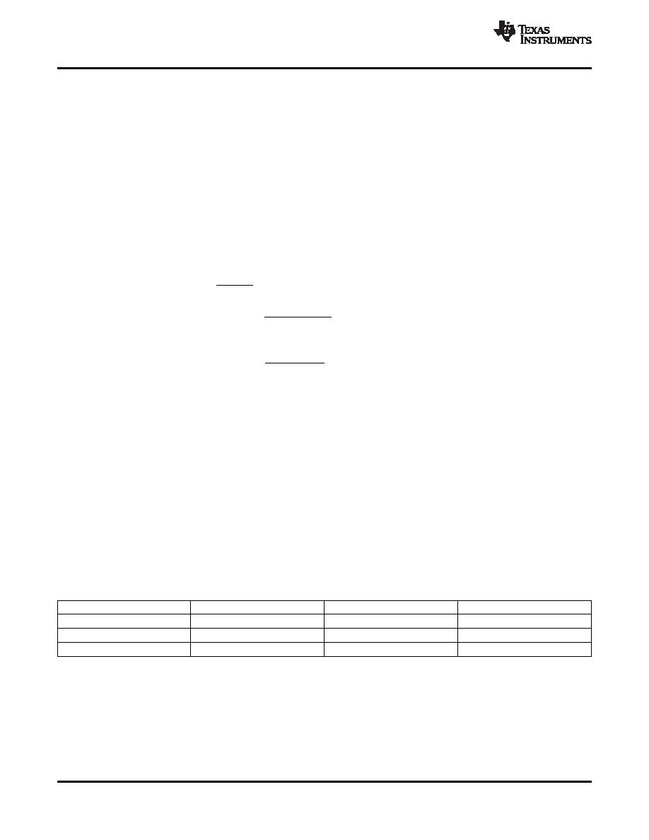
Inductor Selection (Buck Converter)
The buck converter is able to operate with 6.8mH to 15mH inductors, a 10mH inductor is typical. The main
parameter for inductor selection is the saturation current of the inductor which should be higher than the
maximum output current plus the inductor ripple current as calculated in the Design Procedure section. The
highest inductor current occurs at maximum VIN. The alternative more conservative approach is to choose an
inductor with saturation current at least as high as the minimum switch current limit of 1A. Another important
parameter is the inductor dc resistance. Usually the lower the dc resistance the higher the efficiency; the type
and core material of the inductor influences the efficiency as well. The efficiency difference among inductors can
vary up to 10%. Possible inductors are shown in Table 6.
Table 6. Inductor Selection Buck Converter
INDUCTOR VALUE
COMPONENT SUPPLIER
SIZE (L×W×H mm)
Isat/DCR
10mH
Sumida CDRH3D23
3.9 × 3.9 × 2.5
0.85A/95m
10mH
Sumida CDRH3D28
4.0 × 4.0 × 3.0
1.1A/116m
10mH
Sumida CDRH4D22
5.0 × 5.0 × 2.4
0.8A/79m
Rectifier Diode Selection (Buck Converter)
To achieve high efficiency, a Schottky diode should be used. The reverse voltage rating should be higher than
the maximum output voltage of the buck converter. The average rectified forward current Iavg, the Schottky diode
needs to be rated for, is calculated as the off time of the buck converter times the output current.
Iavg = Iout × (1 – D)
(16)
24
Copyright 2009–2010, Texas Instruments Incorporated
Product Folder Link(s): TPS65171
相關PDF資料 |
PDF描述 |
|---|---|
| TPS65182BRGZT | POWER SUPPLY SUPPORT CKT, PQCC48 |
| TPS65182RGZT | POWER SUPPLY SUPPORT CKT, PQCC48 |
| TPS65182RGZR | POWER SUPPLY SUPPORT CKT, PQCC48 |
| TPS65185RSLT | POWER SUPPLY SUPPORT CKT, PQCC48 |
| TPS65200YFFR | 1-CHANNEL POWER SUPPLY SUPPORT CKT, BGA36 |
相關代理商/技術參數 |
參數描述 |
|---|---|
| TPS65175ARSHR | 制造商:Texas Instruments 功能描述:LCD BIAS CHIP AND LEVEL SHIFTE 制造商:Texas Instruments 功能描述:IC BIAS PWR SUPP FOR LCD 56VQFN 制造商:Texas Instruments 功能描述:Fully Programmable LCD Bias IC |
| TPS65175CRSHR | 功能描述:LCD TV/Monitor PMIC 56-VQFN (7x7) 制造商:texas instruments 系列:- 包裝:剪切帶(CT) 零件狀態:有效 應用:LCD 電視機/監控器 電流 - 電源:- 電壓 - 電源:8.6 V ~ 14.7 V 工作溫度:-40°C ~ 85°C 安裝類型:表面貼裝 封裝/外殼:56-VFQFN 裸露焊盤 供應商器件封裝:56-VQFN(7x7) 標準包裝:1 |
| TPS65175RSHR | 功能描述:LCD 驅動器 Fully Programmable LCD Bias IC RoHS:否 制造商:Maxim Integrated 數位數量:4.5 片段數量:30 最大時鐘頻率:19 KHz 工作電源電壓:3 V to 3.6 V 最大工作溫度:+ 85 C 最小工作溫度:- 20 C 封裝 / 箱體:PDIP-40 封裝:Tube |
| TPS65176RHDR | 功能描述:其他電源管理 LCD BIAS IC FOR TV RoHS:否 制造商:Texas Instruments 輸出電壓范圍: 輸出電流:4 mA 輸入電壓范圍:3 V to 3.6 V 輸入電流: 功率耗散: 工作溫度范圍:- 40 C to + 110 C 安裝風格:SMD/SMT 封裝 / 箱體:VQFN-48 封裝:Reel |
| TPS65176RHDT | 功能描述:其他電源管理 LCD BIAS IC FOR TV RoHS:否 制造商:Texas Instruments 輸出電壓范圍: 輸出電流:4 mA 輸入電壓范圍:3 V to 3.6 V 輸入電流: 功率耗散: 工作溫度范圍:- 40 C to + 110 C 安裝風格:SMD/SMT 封裝 / 箱體:VQFN-48 封裝:Reel |
發布緊急采購,3分鐘左右您將得到回復。