- 您現在的位置:買賣IC網 > PDF目錄98301 > TS86101G2BCGL (ATMEL CORP) SERIAL INPUT LOADING, 10-BIT DAC, PBGA255 PDF資料下載
參數資料
| 型號: | TS86101G2BCGL |
| 廠商: | ATMEL CORP |
| 元件分類: | DAC |
| 英文描述: | SERIAL INPUT LOADING, 10-BIT DAC, PBGA255 |
| 封裝: | CBGA-255 |
| 文件頁數: | 29/57頁 |
| 文件大小: | 1119K |
| 代理商: | TS86101G2BCGL |
第1頁第2頁第3頁第4頁第5頁第6頁第7頁第8頁第9頁第10頁第11頁第12頁第13頁第14頁第15頁第16頁第17頁第18頁第19頁第20頁第21頁第22頁第23頁第24頁第25頁第26頁第27頁第28頁當前第29頁第30頁第31頁第32頁第33頁第34頁第35頁第36頁第37頁第38頁第39頁第40頁第41頁第42頁第43頁第44頁第45頁第46頁第47頁第48頁第49頁第50頁第51頁第52頁第53頁第54頁第55頁第56頁第57頁
35
5343C–BDC–03/06
TS86101G2B
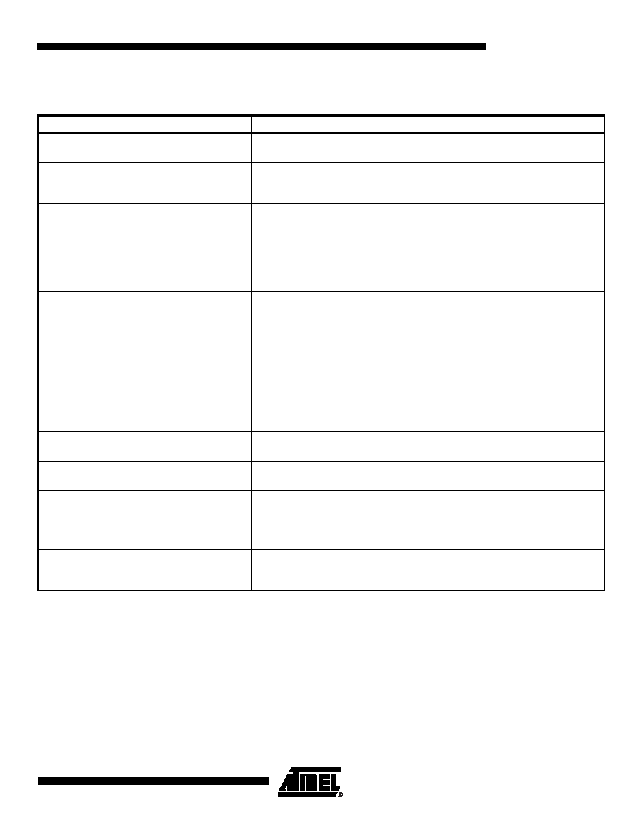
10. Definitions of Terms
Table 3. Definitions of Terms
Abbreviation
Definition
Description
(ACPR)
Adjacent Channel Power
Ratio
The ratio in dB between the power in the adjacent channel and the power in the
channel carrying the modulated signal
(DNL)
Differential Non-linearity
The maximum deviation in the output step size from the ideal value of one least
significant bit (LSB). A DNL of -1 LSB means that a DAC converter guarantees the
transfer function is monotonic
(FSR)
Full-scale Range
The maximum difference between the highest and lowest input levels for which
various device performance specifications prevail, unless otherwise noted
(IMD)
Inter-modulation Distortion
The two tones intermodulation (IMD) rejection is the ratio of either output tone to
the worst intermodulation products. The output tone levels are at -6 dB full-scale
(INL)
Integral Non-linearity
The maximum deviation of the output transfer curve at each code from the ideal
one after the gain and offset error are corrected
(NPR)
Noise Power Ratio
The NPR is measured to characterize the DAC’s capacity to synthesize a
broadband signal. When using a notch-filtered broadband white-noise DAC input
pattern, the Noise Power Ratio is defined as the ratio of the average out-of-notch
to the average in-notch power spectral density magnitude at the DAC’s output
spectrum
(SFDR)
Spurious Free Dynamic
Range
The ratio expressed in dB of the RMS signal amplitude to the RMS value of the
next highest spectral component (peak spurious spectral component) measured
in the frequency band DC to Fclk/2. SFDR is the key parameter for selecting a
converter to be used in a frequency domain application. It may be reported in dBc
(degrades as signal levels are lowered) or in dBFS (always full-scale when related
back to the converter)
(SINAD)
Signal-to-Noise and
Distortion Ratio
The ratio expressed in dB of the RMS signal amplitude to the RMS sum of all
other spectral components, including the harmonics except DC
(SNR)
Signal-to-noise Ratio
The ratio expressed in dB of the RMS signal amplitude to the RMS sum of all
other spectral components excluding the first five harmonics
(THD)
Total Harmonic Distortion
The ratio expressed in dBc of the RMS sum of the first 10 harmonic components,
to the RMS value of the measured fundamental spectral component
TDSP
The time delay between the rising edge of the CW_IN master clock and the active
DSP clock rising edge for a clock shift of 0000
THold
Hold Time
The time difference between the rising edge of the differential Data Ready input
(zero crossing) and a point of change of the digital input data (zero crossing of
differential input)
相關PDF資料 |
PDF描述 |
|---|---|
| TS86101G2BVGL | SERIAL INPUT LOADING, 10-BIT DAC, PBGA255 |
| TS86101G2BMGS | SERIAL INPUT LOADING, 10-BIT DAC, PBGA255 |
| TS86101G2BMGS | PARALLEL, WORD INPUT LOADING, 10-BIT DAC, CBGA255 |
| TS86101G2BVGL | PARALLEL, WORD INPUT LOADING, 10-BIT DAC, CBGA255 |
| TS86101G2BCGL | PARALLEL, WORD INPUT LOADING, 10-BIT DAC, CBGA255 |
相關代理商/技術參數 |
參數描述 |
|---|---|
| TS86101G2BMGS | 制造商:e2v technologies 功能描述:10-BIT DAC MUXDAC 10-BIT 1.2 GSPS - Trays |
| TS86101G2BVGL | 制造商:e2v technologies 功能描述:10-BIT DAC MUXDAC 10-BIT 1.2 GSPS - Trays |
| TS861AI | 制造商:STMICROELECTRONICS 制造商全稱:STMicroelectronics 功能描述:RAIL TO RAIL MICROPOWER BICMOS COMPARATORS |
| TS861AID | 功能描述:校驗器 IC Single Rail-to-Rail RoHS:否 制造商:STMicroelectronics 產品: 比較器類型: 通道數量: 輸出類型:Push-Pull 電源電壓-最大:5.5 V 電源電壓-最小:1.1 V 補償電壓(最大值):6 mV 電源電流(最大值):1350 nA 響應時間: 最大工作溫度:+ 125 C 安裝風格:SMD/SMT 封裝 / 箱體:SC-70-5 封裝:Reel |
| TS861AIDT | 功能描述:校驗器 IC Single Rail-to-Rail RoHS:否 制造商:STMicroelectronics 產品: 比較器類型: 通道數量: 輸出類型:Push-Pull 電源電壓-最大:5.5 V 電源電壓-最小:1.1 V 補償電壓(最大值):6 mV 電源電流(最大值):1350 nA 響應時間: 最大工作溫度:+ 125 C 安裝風格:SMD/SMT 封裝 / 箱體:SC-70-5 封裝:Reel |
發布緊急采購,3分鐘左右您將得到回復。