- 您現在的位置:買賣IC網 > PDF目錄373942 > AD830 (Analog Devices, Inc.) High Speed, Video Difference Amplifier(高速,視頻差分運放) PDF資料下載
參數資料
| 型號: | AD830 |
| 廠商: | Analog Devices, Inc. |
| 元件分類: | 運動控制電子 |
| 英文描述: | High Speed, Video Difference Amplifier(高速,視頻差分運放) |
| 中文描述: | 高速,視頻差分放大器(高速,視頻差分運放) |
| 文件頁數: | 11/16頁 |
| 文件大小: | 244K |
| 代理商: | AD830 |
AD830
REV. A
–11–
Choice of Polarity
T he sign of the gain is easily selected by choosing the polarity of
the connections to the + and – inputs of the X G
M
stage. Swap-
ping between inverting and noninverting gain is possible simply
by reversing the input connections. T he response of the ampli-
fier is identical in either connection, except for the sign change.
T he bandwidth, high impedance, transient behavior, etc., of the
AD830, is symmetrical for both polarities of gain. T his is very
advantageous and unlike an op amp.
Input Impedance
T he relatively high input impedance of the AD830, for a differ-
ential receiver amplifier, permits connections to modest imped-
ance sources without much loading or loss of common-mode
rejection. T he nominal input resistance is 300 k
. T he real limit
to the upper value of the source resistance is in its effect on
common-mode rejection and bandwidth. If the source resistance
is in only one input, then the low frequency common-mode re-
jection will be lowered to
≈
R
IN
/R
S
. T he source resistance/input
f
=
1
2
π×
R
S
×
C
IN
Furthermore, the high frequency common-mode rejection will
be additionally lowered by the difference in the frequency re-
sponse caused by the R
S
3
C
IN
pole. T herefore, to maintain
good low and high frequency common-mode rejection, it is rec-
ommended that the source resistances of the + and – inputs be
matched and of modest value (
≤
10 k
).
Handling Bias Currents
T he bias currents are typically 4
μ
A flowing into each pin of the
G
M
stages of the AD830. Since all applications possess some fi-
nite source resistance, the bias current through this resistor will
create a voltage drop (I
BIAS
3
R
S
). T he relatively high input im-
pedance of the AD830 permits modest values of R
S
, typically
≤
10 k
. If the source resistance is in only one terminal, then an
objectional offset voltage may result (e.g., 4
μ
A
3
5 k
=
20 mV). Placement of an equal value resistor in series with the
other input will cancel the offset to first order. However, due to
mismatches in the resistances, a residual offset will remain and
likely be greater than bias current (offset current) mismatches.
capacitance pole
limits the bandwidth.
Applying Feedback
T he AD830 is intended for use with gain from 1 to 100. Gains
greater than one are simply set by a pair of resistors connected
as shown in the difference amplifier (Figure 35) with gain >1.
T he value of the bottom resistor R
2
, should be kept less than
1 k
to insure that the pole formed by C
IN
and the parallel con-
nection of R
1
and R
2
is sufficiently high in frequency so that it
does not introduce excessive phase shift around the loop and de-
stabilizes the amplifier. A compensating resistor, equal to the
parallel combination of R
1
and R
2
, should be placed in series
with the other Y G
M
stage input to preserve the high frequency
common-mode rejection and to lower the offset voltage induced
by the input bias current.
Output Common Mode
T he output swing of the AD830 is defined by the differential in-
put voltage, the gain and the output common. Depending on
the anticipated signal span, the output common (or ground)
may be set anywhere between the allowable peak output voltage
in a manner similar to that described for input voltage common
mode. A plot of the peak output voltage versus supply is shown
in Figure 26. A prediction of the common-mode range versus
the peak output differential voltage can be easily derived from
the maximum output swing as V
OCM
= V
MAX
–V
PEAK
.
Output Current
T he absolute peak output current is set by the short circuit cur-
rent limiting, typically greater that 60 mA. T he maximum drive
capability is rated at 50 mA, but without a guarantee of distor-
tion performance. Best distortion performance is obtained by
keeping the output current
≤
20 mA. Attempting to drive large
voltages into low valued resistances (e.g., 10 V into 150
) will
cause an apparent lowering of the limit for output signal swing,
but is just the current limiting behavior.
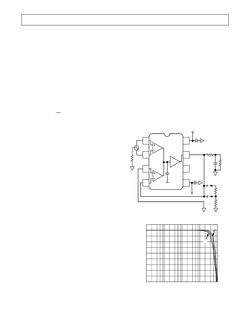
Driving Cap Loads
T he AD830 is capable of driving modest sized capacitive loads
while maintaining its rated performance. Several curves of band-
width versus capacitive load are given in Figures 15 and 18. T he
AD830 was designed primarily as a low distortion video speed
amplifier, but with a tradeoff, giving up very large capacitive
load driving capability. If very large capacitive loads must be
driven, then the network shown in Figure 27 should be used to
insure stable operation. If the loss of gain caused by the resistor
R
S
in series with the load is objectionable, then the optional
feedback network shown may be added to restore the lost gain.
5
8
4
1
2
3
7
6
A=1
AD830
G
M
C
G
M
+
–
INPUT
SIGNAL
+V
S
0.1
μ
F
R
S
36.5
V
OUT
R
S
C
1
100pF
R
1
1k
R
1
0.1
μ
F
–V
S
* OPTIONAL
FEEDBACK
NETWORK
Z
CM
V
CM
Figure 27. Circuit for Driving Large Capacitive Loads
3
–12
–27
100k
100M
10M
1M
10k
–9
–6
–3
0
–24
–21
–18
–15
C
FREQUENCY – Hz
±
15V
±
5V
Figure 28. Closed-Loop Response vs. Frequency with
100 pF Load and Series Resistor Compensation
相關PDF資料 |
PDF描述 |
|---|---|
| AD8313ARM-REEL7 | 0.1 GHz-2.5 GHz, 70 dB Logarithmic Detector/Controller |
| AD8313ARM | 0.1 GHz-2.5 GHz, 70 dB Logarithmic Detector/Controller |
| AD8313ARM-REEL | 0.1 GHz-2.5 GHz, 70 dB Logarithmic Detector/Controller |
| AD8313-EVAL | 0.1 GHz-2.5 GHz, 70 dB Logarithmic Detector/Controller |
| AD8313 | 0.1 GHz-2.5 GHz,70dB Logarithmic Detector/Controller(頻率為0.1 GHz-2.5 GHz,增益為70dB的對數檢測器/控制器) |
相關代理商/技術參數 |
參數描述 |
|---|---|
| AD830_10 | 制造商:AD 制造商全稱:Analog Devices 功能描述:High Speed, Video Difference Amplifier |
| AD8300 | 制造商:AD 制造商全稱:Analog Devices 功能描述:+3 Volt, Serial Input Complete 12-Bit DAC |
| AD8300AN | 功能描述:IC DAC 12-BIT SERIAL 8-DIP RoHS:否 類別:集成電路 (IC) >> 數據采集 - 數模轉換器 系列:- 標準包裝:2,400 系列:- 設置時間:- 位數:18 數據接口:串行 轉換器數目:3 電壓電源:模擬和數字 功率耗散(最大):- 工作溫度:-40°C ~ 85°C 安裝類型:表面貼裝 封裝/外殼:36-TFBGA 供應商設備封裝:36-TFBGA 包裝:帶卷 (TR) 輸出數目和類型:* 采樣率(每秒):* |
| AD8300ANZ | 功能描述:IC DAC 12BIT SERIAL 8DIP RoHS:是 類別:集成電路 (IC) >> 數據采集 - 數模轉換器 系列:- 標準包裝:1 系列:- 設置時間:4.5µs 位數:12 數據接口:串行,SPI? 轉換器數目:1 電壓電源:單電源 功率耗散(最大):- 工作溫度:-40°C ~ 125°C 安裝類型:表面貼裝 封裝/外殼:8-SOIC(0.154",3.90mm 寬) 供應商設備封裝:8-SOICN 包裝:剪切帶 (CT) 輸出數目和類型:1 電壓,單極;1 電壓,雙極 采樣率(每秒):* 其它名稱:MCP4921T-E/SNCTMCP4921T-E/SNRCTMCP4921T-E/SNRCT-ND |
| AD8300AR | 功能描述:IC DAC 12BIT 3V SRL-IN 8-SOIC RoHS:否 類別:集成電路 (IC) >> 數據采集 - 數模轉換器 系列:- 標準包裝:47 系列:- 設置時間:2µs 位數:14 數據接口:并聯 轉換器數目:1 電壓電源:單電源 功率耗散(最大):55µW 工作溫度:-40°C ~ 85°C 安裝類型:表面貼裝 封裝/外殼:28-SSOP(0.209",5.30mm 寬) 供應商設備封裝:28-SSOP 包裝:管件 輸出數目和類型:1 電流,單極;1 電流,雙極 采樣率(每秒):* |
發布緊急采購,3分鐘左右您將得到回復。