- 您現(xiàn)在的位置:買賣IC網(wǎng) > Datasheet目錄39 > ADT7482ARMZ-REEL (ON Semiconductor)IC SENSOR TEMP 2CH ALARM 10MSOP Datasheet資料下載
參數(shù)資料
| 型號: | ADT7482ARMZ-REEL |
| 廠商: | ON Semiconductor |
| 文件頁數(shù): | 16/20頁 |
| 文件大小: | 282K |
| 描述: | IC SENSOR TEMP 2CH ALARM 10MSOP |
| 產(chǎn)品變化通告: | MFG CHG Notification ADI to ON Semi |
| 標(biāo)準(zhǔn)包裝: | 3,000 |
| 功能: | 溫度監(jiān)控系統(tǒng)(傳感器) |
| 傳感器類型: | 內(nèi)部和外部 |
| 感應(yīng)溫度: | -40°C ~ 125°C,外部傳感器 |
| 精確度: | ±2.5°C(最小值) |
| 拓?fù)洌?/td> | ADC,比較器,多路復(fù)用器,寄存器庫 |
| 輸出類型: | SMBus? |
| 輸出警報(bào): | 是 |
| 輸出風(fēng)扇: | 是 |
| 電源電壓: | 3 V ~ 3.6 V |
| 工作溫度: | -40°C ~ 125°C |
| 安裝類型: | 表面貼裝 |
| 封裝/外殼: | 10-TFSOP,10-MSOP(0.118",3.00mm 寬) |
| 供應(yīng)商設(shè)備封裝: | 10-MSOP |
| 包裝: | 帶卷 (TR) |
ADT7482
http://onsemi.com
16
where a remote diode is not connected, or is incorrectly
connected, to the ADT7482. A simple voltage comparator
trips if the voltage at D+ exceeds V
DD
1 V (typical),
signifying an open circuit between D+ and D. The output
of this comparator is checked when a conversion is initiated.
Bit 2 (D1 OPEN flag) of the Status Register 1
(Address 0x02) is set if a fault is detected on the Remote 1
channel. Bit 2 (D2 OPEN flag) of the Status Register 2
(Address 0x23) is set if a fault is detected on the Remote 2
channel. If the ALERT
pin is enabled, setting this flag causes
ALERT
to assert low.
If a remote sensor is not used with the ADT7482, then the
D+ and D inputs of the ADT7482 need to be tied together
to prevent the OPEN flag from being set continuously.
Most temperature sensing diodes have an operating
temperature range of 55癈 to +150癈. Above 150癈, they
lose their semiconductor characteristics and approximate
conductors instead. This results in a diode short, setting the
open flag. The remote diode in this case no longer gives an
accurate temperature measurement. A read of the
temperature result register gives the last good temperature
measurement. Be aware that while the diode fault is
triggered, the temperature measurement on the remote
channels may not be accurate.
Interrupt System
The ADT7482 has two interrupt outputs, ALERT
and
THERM
. Both have different functions and behavior.
ALERT
is maskable and responds to violations of software
programmed temperature limits or an open-circuit fault on
the remote diode. THERM
is intended as a fail-safe interrupt
output that cannot be masked.
If the Remote 1, Remote 2, or local temperature exceeds
the programmed high temperature limits, or equals or
exceeds the low temperature limits, the ALERT
output is
asserted low. An open-circuit fault on the remote diode also
causes ALERT
to assert. ALERT
is reset when serviced by
a master reading its device address, provided the error
condition has gone away, and the status register has been
reset.
The THERM
output asserts low if the Remote 1,
Remote 2, or local temperature exceeds the programmed
THERM
limits. The THERM
temperature limits should
normally be equal to or greater than the high temperature
limits. THERM
is reset automatically when the temperature
falls back within the (THERM
hysteresis) limit. The local
and remote THERM
limits are set by default to 85癈. A
hysteresis value can be programmed, in which case,
THERM
resets when the temperature falls to the limit value
minus the hysteresis value. This applies to both local and
remote measurement channels. The power-on hysteresis
default value is 10癈, but this can be reprogrammed to any
value after powerup.
The hysteresis loop on the THERM
outputs is useful when
THERM
is used for on/off control of a fan. The system can
be set up so that when THERM
asserts, a fan can be switched
on to cool the system. When THERM
goes high again, the
fan can be switched off. Programming a hysteresis value
protects from fan jitter, where the temperature hovers
around the THERM
limit, and the fan is constantly being
switched on and off.
Table 17. THERM
HYSTERESIS
THERM
Hysteresis
Binary Representation
0癈
0 000 0000
1癈
0 000 0001
10癈
0 000 1010
If the ADT7482 is in the default temperature range (0癈
to 127癈), then THERM
hysteresis must be less than the
THERM
limit.
Figure 20 shows how the THERM
and ALERT
outputs
operate. If desired, use the ALERT
output as a SMBALERT
to signal to the host via the SMBus that the temperature has
risen. Use the THERM
output to turn on a fan to cool the
system, if the temperature continues to increase. This
method ensures that there is a fail-safe mechanism to cool
the system, without the need for host intervention.
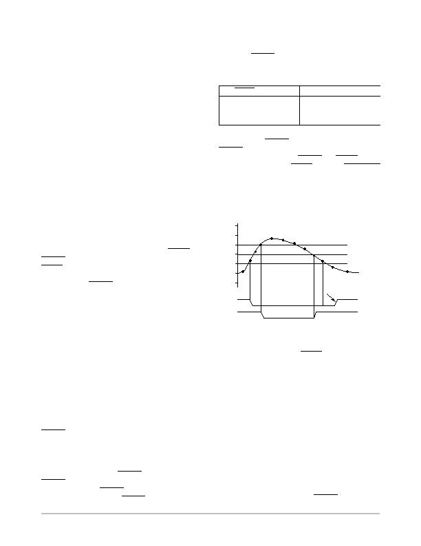
Figure 20. Operation of the ALERT
and THERM
Interrupts
1005C
THERM
LIMIT
905C
805C
705C
605C
505C
405C
THERM
LIMIT HYSTERESIS
HIGH TEMP LIMIT
RESET BY MASTER
TEMPERATURE
1
2
3
4
ALERT
THERM
1. If the measured temperature exceeds the high
temperature limit, the ALERT
output asserts low.
2. If the temperature continues to increase and
exceeds the THERM
limit, the THERM
output
asserts low. This can be used to throttle the CPU
clock or switch on a fan.
3. The THERM
output de-asserts (goes high) when
the temperature falls to THERM
limit minus
hysteresis. In Figure 20, the default hysteresis
value of 10癈 is shown.
4. The ALERT
output de-asserts only when the
temperature has fallen below the high temperature
limit, and the master has read the device address
and cleared the status register.
Pin 8 on the ADT7482 can be configured as either an
ALERT
output or as an additional THERM
output.
THERM2
asserts low when the temperature exceeds the
programmed local and/or remote high temperature limits. It
is reset in the same manner as THERM
, and it is not
相關(guān)PDF資料 |
PDF描述 |
|---|---|
| ADT7485AARMZ-R | IC TEMP/VOLT DGL SENS SST 10MSOP |
| ADT7486AARMZ-RL | IC TEMP SENS DGTL 2CH SST 10MSOP |
| ADT7488AARMZ-RL | IC TEMP/VOLT DGTL W/SST 10MSOP |
| ADT7518ARQZ | IC SENSOR TEMP QD ADC/DAC 16QSOP |
| AT30TS00-MAH-T | SENSOR DGTL TEMP I2C/SMBUS 8WDFN |
相關(guān)代理商/技術(shù)參數(shù) |
參數(shù)描述 |
|---|---|
| ADT7482ARMZ-REEL7 | 功能描述:IC SENSOR TEMP 2CH ALARM 10MSOP RoHS:是 類別:集成電路 (IC) >> PMIC - 熱管理 系列:- 標(biāo)準(zhǔn)包裝:1 系列:- 功能:溫度監(jiān)控系統(tǒng)(傳感器) 傳感器類型:內(nèi)部和外部 感應(yīng)溫度:-40°C ~ 125°C,外部傳感器 精確度:±2.5°C 本地(最大值),±5°C 遠(yuǎn)程(最大值) 拓?fù)?ADC,比較器,寄存器庫 輸出類型:2 線 SMBus? 輸出警報(bào):無 輸出風(fēng)扇:無 電源電壓:2.7 V ~ 5.5 V 工作溫度:-40°C ~ 125°C 安裝類型:表面貼裝 封裝/外殼:SOT-23-8 供應(yīng)商設(shè)備封裝:SOT-23-8 包裝:Digi-Reel® 其它名稱:296-22675-6 |
| ADT7482ARMZ-RL7 | 功能描述:板上安裝溫度傳感器 2 CH TEMP SNSR/ALARM 2 WIRE SMBUS INTRFCE RoHS:否 制造商:Omron Electronics 輸出類型:Digital 配置: 準(zhǔn)確性:+/- 1.5 C, +/- 3 C 溫度閾值: 數(shù)字輸出 - 總線接口:2-Wire, I2C, SMBus 電源電壓-最大:5.5 V 電源電壓-最小:4.5 V 最大工作溫度:+ 50 C 最小工作溫度:0 C 關(guān)閉: 安裝風(fēng)格: 封裝 / 箱體: 設(shè)備功能:Temperature and Humidity Sensor |
| ADT7483A | 制造商:AD 制造商全稱:Analog Devices 功能描述:Dual Channel Temperature Sensor and Over Temperature Alarm |
| ADT7483AARQZ | 功能描述:板上安裝溫度傳感器 2 TEMP DIODE MONITOR 2 WIRE SMBUS INTRFCE RoHS:否 制造商:Omron Electronics 輸出類型:Digital 配置: 準(zhǔn)確性:+/- 1.5 C, +/- 3 C 溫度閾值: 數(shù)字輸出 - 總線接口:2-Wire, I2C, SMBus 電源電壓-最大:5.5 V 電源電壓-最小:4.5 V 最大工作溫度:+ 50 C 最小工作溫度:0 C 關(guān)閉: 安裝風(fēng)格: 封裝 / 箱體: 設(shè)備功能:Temperature and Humidity Sensor |
| ADT7483AARQZ-R7 | 功能描述:板上安裝溫度傳感器 2 TEMP DIODE MONITOR 2 WIRE SMBUS INTRFCE RoHS:否 制造商:Omron Electronics 輸出類型:Digital 配置: 準(zhǔn)確性:+/- 1.5 C, +/- 3 C 溫度閾值: 數(shù)字輸出 - 總線接口:2-Wire, I2C, SMBus 電源電壓-最大:5.5 V 電源電壓-最小:4.5 V 最大工作溫度:+ 50 C 最小工作溫度:0 C 關(guān)閉: 安裝風(fēng)格: 封裝 / 箱體: 設(shè)備功能:Temperature and Humidity Sensor |
發(fā)布緊急采購,3分鐘左右您將得到回復(fù)。