- 您現在的位置:買賣IC網 > PDF目錄30743 > LM1253AAE/NA (NATIONAL SEMICONDUCTOR CORP) ON-SCREEN DISPLAY IC, PDIP28 PDF資料下載
參數資料
| 型號: | LM1253AAE/NA |
| 廠商: | NATIONAL SEMICONDUCTOR CORP |
| 元件分類: | 畫面疊加 |
| 英文描述: | ON-SCREEN DISPLAY IC, PDIP28 |
| 封裝: | 0.600 INCH, PLASTIC, DIP-28 |
| 文件頁數: | 5/61頁 |
| 文件大小: | 1671K |
| 代理商: | LM1253AAE/NA |
第1頁第2頁第3頁第4頁當前第5頁第6頁第7頁第8頁第9頁第10頁第11頁第12頁第13頁第14頁第15頁第16頁第17頁第18頁第19頁第20頁第21頁第22頁第23頁第24頁第25頁第26頁第27頁第28頁第29頁第30頁第31頁第32頁第33頁第34頁第35頁第36頁第37頁第38頁第39頁第40頁第41頁第42頁第43頁第44頁第45頁第46頁第47頁第48頁第49頁第50頁第51頁第52頁第53頁第54頁第55頁第56頁第57頁第58頁第59頁第60頁第61頁
Pin Descriptions (Continued)
Pin 20 — Digital Supply 5V supply for the OSD section of
the LM1253A. Pins 19 and 20 should be tied together under
normal operating conditions.
Pin 21 — Analog Supply 5V supply for the video section of
the preamp. A 0.1 F capacitor should be connected be-
tween pin 21 and pin 22, as close as possible to the
LM1253A.
Pin 22 — Analog Ground Ground for the video section of
the LM1253A. All ground pins of the LM1253A should be
connected together by a ground plane under the LM1253A.
See
Figure 31, which shows a sample layout.
Pin 23, 24, and 25 — Green, Red, and Blue Video Out
These pins output the red, green, and blue video information
in the VideoPlex format. These pins are connected to the
LM2453 using as short of traces as possible. An inductor
should be in series with the trace between the preamp and
CRT driver. The value of this inductor depends on the board
layout.
Figures 29, 30 show the external schematic of pins
23, 24, and 25,
Figure 21 shows the internal schematic.
Pin 26 — V
REF Out The voltage that the VideoPlex signal is
referenced to is output on this pin. A 0.1 F capacitor should
be connected between this pin and ground and be located
close to the LM1253A. This pin is connected to the V
REF pin
of the LM2453. A 0.1 F capacitor also needs to be con-
nected very close to the LM2453. A 100 F capacitor should
also be connected to this trace.
Figures 29, 30 show the
external schematic of pin 26,
Figure 22 shows the internal
schematic.
Pin 27 — Analog Ground Ground for the band gap refer-
ence section of the LM1253A. All ground pins of the
LM1253A should be connected together by a ground plane
under the LM1253A. See
Figure 31, which shows a sample
layout.
Pin 28 — Analog Supply 5V supply for the band gap refer-
ence section of the preamp. A 0.1 F capacitor should be
connected between pin 27 and pin 28, as close as possible
to the LM1253A. See
Figure 31, which shows a sample
layout.
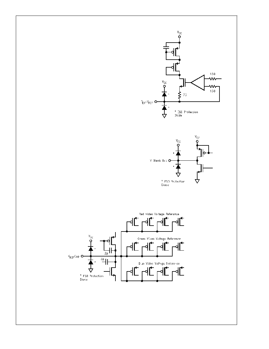
Input/Output Schematics
DS101265-14
FIGURE 11. Pin 1 (R
EXT VREF)
DS101265-15
FIGURE 12. Pin 2 (V Blank Out)
DS101265-16
FIGURE 13. Pin 3 (V
REF Cap)
LM1253A
www.national.com
13
相關PDF資料 |
PDF描述 |
|---|---|
| LM1267NA/NOPB | 3 CHANNEL, VIDEO PREAMPLIFIER, PDIP24 |
| LM1269NA/NOPB | 3 CHANNEL, VIDEO PREAMPLIFIER, PDIP24 |
| LM1276AAA/NA | 1 CHANNEL, VIDEO PREAMPLIFIER, PDIP28 |
| LM1279AN/NOPB | 3 CHANNEL, VIDEO AMPLIFIER, PDIP20 |
| LM1279N/NOPB | 1 CHANNEL, VIDEO AMPLIFIER, PDIP20 |
相關代理商/技術參數 |
參數描述 |
|---|---|
| LM1253AN | 制造商:NSC 制造商全稱:National Semiconductor 功能描述:Monolithic Triple 180 MHz I2C CRT Pre-amp With Integrated Analog On Screen Display (OSD) Generator |
| LM-1256 | 制造商:ROHM 制造商全稱:Rohm 功能描述:16 x 16 matrix displays |
| LM-1256_1 | 制造商:ROHM 制造商全稱:Rohm 功能描述:16】16 matrix displays |
| LM-1256LB1 | 制造商:ROHM 制造商全稱:Rohm 功能描述:16】16 matrix displays |
| LM125AN | 制造商:NSC 制造商全稱:National Semiconductor 功能描述:VOLTAGE REGULATORS |
發布緊急采購,3分鐘左右您將得到回復。