- 您現在的位置:買賣IC網 > PDF目錄361138 > NSS20201MR6 (ON SEMICONDUCTOR) 20 V, 3 A, Low VCE(sat) NPN Transistor PDF資料下載
參數資料
| 型號: | NSS20201MR6 |
| 廠商: | ON SEMICONDUCTOR |
| 英文描述: | 20 V, 3 A, Low VCE(sat) NPN Transistor |
| 中文描述: | 20五,3甲,低Vce(sat)NPN晶體管 |
| 文件頁數: | 1/4頁 |
| 文件大小: | 38K |
| 代理商: | NSS20201MR6 |
Semiconductor Components Industries, LLC, 2005
June, 2005 Rev. P1
1
Publication Order Number:
NSS20201MR6/D
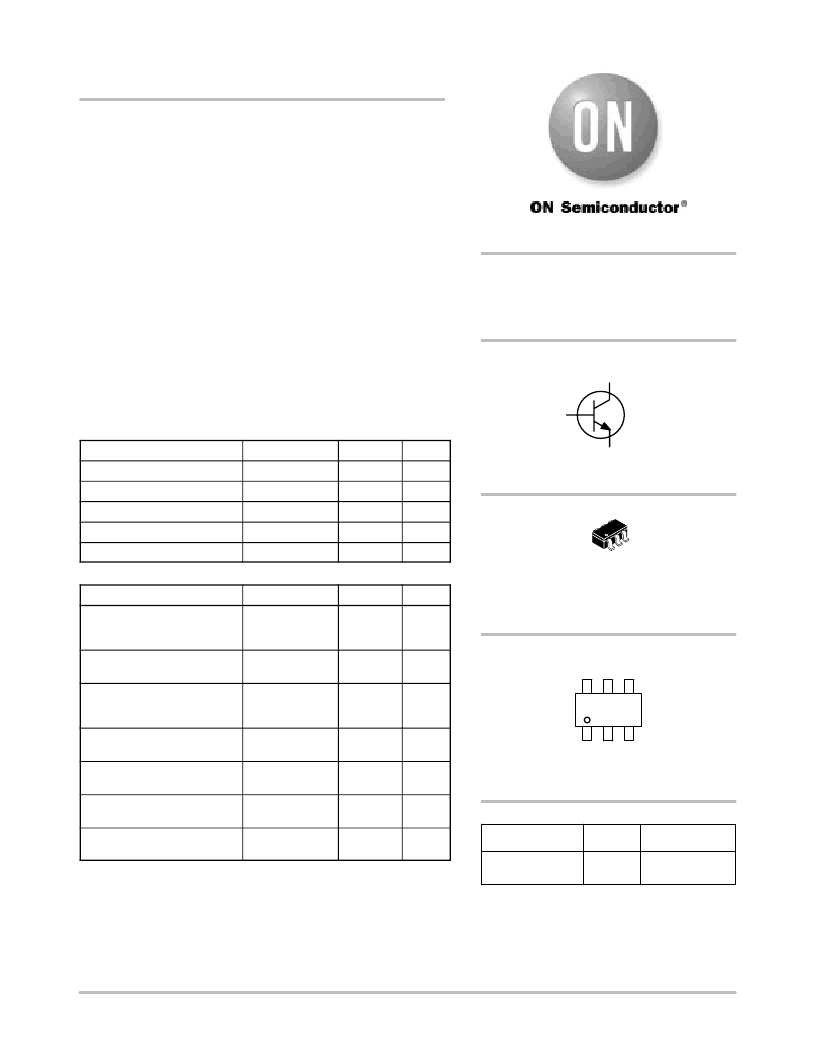
NSS20201MR6T1G
Product Preview
20 V, 3 A, Low V
CE(sat)
NPN Transistor
ON Semiconductor’s e
2
PowerEdge family of low V
CE(sat)
transistors
are miniature surface mount devices featuring ultra low
saturation voltage (V
CE(sat)
) and high current gain capability. These
are designed for use in low voltage, high speed switching applications
where affordable efficient energy control is important.
Typical application are DCDC converters and power management
in portable and battery powered products such as cellular and cordless
phones, PDAs, computers, printers, digital cameras and MP3 players.
Other applications are low voltage motor controls in mass storage
products such as disc drives and tape drives. In the automotive
industry they can be used in air bag deployment and in the instrument
cluster. The high current gain allows e
2
PowerEdge devices to be
driven directly from PMU’s control outputs, and the Linear Gain
(Beta) makes them ideal components in analog amplifiers.
MAXIMUM RATINGS
(T
A
= 25
°
C)
Rating
Symbol
Max
Unit
Collector-Emitter Voltage
V
CEO
20
V
Collector-Base Voltage
V
CBO
40
V
Emitter-Base Voltage
V
EBO
5.0
V
Collector Current Continuous
I
C
2.0
A
Collector Current Peak
I
CM
3.0
A
THERMAL CHARACTERISTICS
Characteristic
Symbol
Max
Unit
Total Device Dissipation
T
A
= 25
°
C
Derate above 25
°
C
P
D
(Note 1)
535
4.3
mW
mW/
°
C
Thermal Resistance,
JunctiontoAmbient
R
JA
(Note 1)
234
°
C/W
Total Device Dissipation
T
= 25
°
C
Derate above 25
°
C
P
D
(Note 2)
1.180
9.4
W
mW/
°
C
Thermal Resistance,
JunctiontoAmbient
R
JA
(Note 2)
106
°
C/W
Thermal Resistance,
JunctiontoLead #1
R
JL
(Note 1)
R
JL
(Note 2)
110
50
°
C/W
°
C/W
Total Device Dissipation
(Single Pulse < 10 s)
P
Dsingle
(Note 2)
1.75
W
Junction and Storage
Temperature Range
T
J
, T
stg
55 to
+150
°
C
Maximum ratings are those values beyond which device damage can occur.
Maximum ratings applied to the device are individual stress limit values (not
normal operating conditions) and are not valid simultaneously. If these limits are
exceeded, device functional operation is not implied, damage may occur and
reliability may be affected.
1. FR4 with 1 oz and 3.9 mm
2
of copper area.
2. FR4 with 1 oz and 645 mm
2
of copper area.
This document contains information on a product under development. ON Semiconductor
reserves the right to change or discontinue this product without notice.
Device
Package
Shipping
ORDERING INFORMATION
NSS20201MR6T1G
TSOP6
(PbFree)
CASE 318G
TSOP6
STYLE 6
3000/Tape & Reel
DEVICE MARKING
4
5
6
3
2
1
COLLECTOR
1, 2, 5, 6
3
BASE
4
EMITTER
VS0
VS0= Specific Device Code
d
= Date Code
For information on tape and reel specifications,
including part orientation and tape sizes, please
refer to our Tape and Reel Packaging Specifications
Brochure, BRD8011/D.
http://onsemi.com
20 VOLTS
3.0 AMPS
NPN LOW V
CE(sat)
TRANSISTOR
EQUIVALENT R
DS(on)
100 m
相關PDF資料 |
PDF描述 |
|---|---|
| NSS20201MR6D | 20 V, 3 A, Low VCE(sat) NPN Transistor |
| NSS20201MR6T1G | 20 V, 3 A, Low VCE(sat) NPN Transistor |
| NSS30070MR6T1G | 30 V, 0.7 A, Low VCE(sat) PNP Transistor(30V, 0.7A, 低VCE(sat) PNP晶體管) |
| NST30010MXV6T1G | Dual Matched General Purpose Transistor(雙通用晶體管) |
| NST3946DW1T1 | Dual General Purpose Transistor |
相關代理商/技術參數 |
參數描述 |
|---|---|
| NSS20201MR6D | 制造商:ONSEMI 制造商全稱:ON Semiconductor 功能描述:20 V, 3 A, Low VCE(sat) NPN Transistor |
| NSS20201MR6T1G | 功能描述:兩極晶體管 - BJT 2A 20V Low VCEsat RoHS:否 制造商:STMicroelectronics 配置: 晶體管極性:PNP 集電極—基極電壓 VCBO: 集電極—發射極最大電壓 VCEO:- 40 V 發射極 - 基極電壓 VEBO:- 6 V 集電極—射極飽和電壓: 最大直流電集電極電流: 增益帶寬產品fT: 直流集電極/Base Gain hfe Min:100 A 最大工作溫度: 安裝風格:SMD/SMT 封裝 / 箱體:PowerFLAT 2 x 2 |
| NSS20201MR6T1G_06 | 制造商:ONSEMI 制造商全稱:ON Semiconductor 功能描述:20 V, 3 A, Low VCE(sat) NPN Transistor |
| NSS20300MR6T1G | 功能描述:兩極晶體管 - BJT 3A 20V Low VCEsat RoHS:否 制造商:STMicroelectronics 配置: 晶體管極性:PNP 集電極—基極電壓 VCBO: 集電極—發射極最大電壓 VCEO:- 40 V 發射極 - 基極電壓 VEBO:- 6 V 集電極—射極飽和電壓: 最大直流電集電極電流: 增益帶寬產品fT: 直流集電極/Base Gain hfe Min:100 A 最大工作溫度: 安裝風格:SMD/SMT 封裝 / 箱體:PowerFLAT 2 x 2 |
| NSS20300MR6T1G_07 | 制造商:ONSEMI 制造商全稱:ON Semiconductor 功能描述:20 V, 5 A, Low VCE(sat) PNP Transistor |
發布緊急采購,3分鐘左右您將得到回復。