- 您現在的位置:買賣IC網 > PDF目錄382380 > PCD5008 (NXP Semiconductors N.V.) FLEX Pager Decoder PDF資料下載
參數資料
| 型號: | PCD5008 |
| 廠商: | NXP Semiconductors N.V. |
| 英文描述: | FLEX Pager Decoder |
| 中文描述: | FleX創建傳呼機解碼器 |
| 文件頁數: | 16/64頁 |
| 文件大?。?/td> | 341K |
| 代理商: | PCD5008 |
第1頁第2頁第3頁第4頁第5頁第6頁第7頁第8頁第9頁第10頁第11頁第12頁第13頁第14頁第15頁當前第16頁第17頁第18頁第19頁第20頁第21頁第22頁第23頁第24頁第25頁第26頁第27頁第28頁第29頁第30頁第31頁第32頁第33頁第34頁第35頁第36頁第37頁第38頁第39頁第40頁第41頁第42頁第43頁第44頁第45頁第46頁第47頁第48頁第49頁第50頁第51頁第52頁第53頁第54頁第55頁第56頁第57頁第58頁第59頁第60頁第61頁第62頁第63頁第64頁
1998 Jun 17
16
Philips Semiconductors
Product specification
FLEX
Pager Decoder
PCD5008
8.4.3
C
ONFIGURATION SEQUENCE
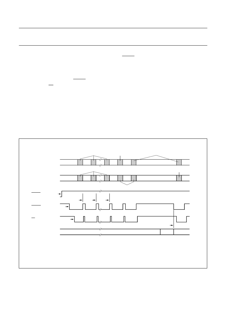
A typical configuration and synchronisation sequence
would be as follows, see Fig.11 for event timings:
1.
The PCD5008 is reset by the host.
2.
After 1 second the PCD5008 interrupts the host to
read the part ID by pulling the READY line LOW.
3.
The host pulls SS LOW at the start of each
SPI transfer and clocks out the part ID data.
4.
The host configures the following aspects of PCD5008
operation:
a) General configuration (Section 8.4.4)
b) Receiver operation (Section 8.5)
c) FLEX
CAPCODE configuration (Section 8.6).
The PCD5008 writes a part ID packet in response to
each incoming packet.
5.
At the end of each packet the PCD5008 pulls the
READY line HIGH, and then LOW again to indicate
that packet processing is complete.
The host writes a control packet to enable FLEX
decoding in the PCD5008 (Section 8.4.7).
The host writes a checksum packet to enable SPI data
output by the PCD5008 (Section 8.4.2).
On recognising a SYNC word, the PCD5008
synchronises to the channel.
The PCD5008 initiates an SPI transfer writing the
status packet, indicating that it is now in synchronous
mode.
6.
7.
8.
9.
Fig.11 Typical configuration and synchronisation sequence.
handbook, full pagewidth
MBK097
SPI
DECODER-TO-HOST
RESET
READY
SS
FLEX DATASTREAM
SPI
HOST-TO-DECODER
checksum packet
(7)
control packet
(6)
partid packet
(4)
configuration packets
(addresses, receiver etc.)
status packet
(9)
partid packet
(4)
(1)
(2)
(3)
(5)
(5)
(5)
(8)
SYNC
Numbers within parenthesis refer to sequence numbers, see Section 8.4.3.
相關PDF資料 |
PDF描述 |
|---|---|
| PCD5008H | FLEX Pager Decoder |
| PCD5013 | FLEX roaming decoder II |
| PCD5013H | FLEX roaming decoder II |
| PCD5032 | ADPCM CODEC for digital cordless telephones |
| PCD5032H | ADPCM CODEC for digital cordless telephones |
相關代理商/技術參數 |
參數描述 |
|---|---|
| PCD5008H | 制造商:PHILIPS 制造商全稱:NXP Semiconductors 功能描述:FLEX Pager Decoder |
| PCD5008HBD-T | 制造商:未知廠家 制造商全稱:未知廠家 功能描述:Telecommunication Decoder |
| PCD5013 | 制造商:PHILIPS 制造商全稱:NXP Semiconductors 功能描述:FLEX roaming decoder II |
| PCD5013H | 制造商:PHILIPS 制造商全稱:NXP Semiconductors 功能描述:FLEX roaming decoder II |
| PCD5032 | 制造商:PHILIPS 制造商全稱:NXP Semiconductors 功能描述:ADPCM CODEC for digital cordless telephones |
發布緊急采購,3分鐘左右您將得到回復。