- 您現在的位置:買賣IC網 > PDF目錄382380 > PCD5008 (NXP Semiconductors N.V.) FLEX Pager Decoder PDF資料下載
參數資料
| 型號: | PCD5008 |
| 廠商: | NXP Semiconductors N.V. |
| 英文描述: | FLEX Pager Decoder |
| 中文描述: | FleX創建傳呼機解碼器 |
| 文件頁數: | 24/64頁 |
| 文件大小: | 341K |
| 代理商: | PCD5008 |
第1頁第2頁第3頁第4頁第5頁第6頁第7頁第8頁第9頁第10頁第11頁第12頁第13頁第14頁第15頁第16頁第17頁第18頁第19頁第20頁第21頁第22頁第23頁當前第24頁第25頁第26頁第27頁第28頁第29頁第30頁第31頁第32頁第33頁第34頁第35頁第36頁第37頁第38頁第39頁第40頁第41頁第42頁第43頁第44頁第45頁第46頁第47頁第48頁第49頁第50頁第51頁第52頁第53頁第54頁第55頁第56頁第57頁第58頁第59頁第60頁第61頁第62頁第63頁第64頁
1998 Jun 17
24
Philips Semiconductors
Product specification
FLEX
Pager Decoder
PCD5008
8.5.6
A
CTIVE RECEIVER STATES
8.5.6.1
General
In addition to the warm-up and shut-down states, the PCD5008 has four active receiver states. When these settings are
applied to the receiver control lines, the PCD5008 is decoding the EXTS1 and EXTS0 input signals. The timing of these
signals and their duration depends on the FLEX
data stream. Because of this, there is no time setting associated with
these settings (with the exception of the 3200 sps sync setting).
The four settings are as follows:
1600 sps sync setting:
applied when the PCD5008 searches for a 1600 sps signal.
3200 sps sync setting:
applied when the PCD5008 searches for a 3200 sps signal.
1600 sps data setting:
applied after the PCD5008 has found the C or C sync word in the sync 2 section of a
1600 sps frame.
3200 sps data setting:
applied after the PCD5008 has found the C or C sync word in the sync 2 section of a
3200 sps frame.
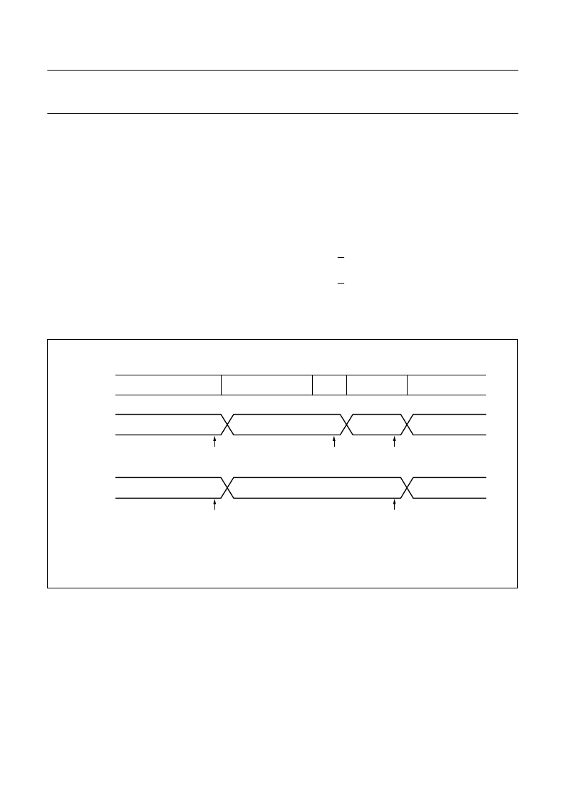
Figure 14 shows some examples of how these settings are used in the PCD5008.
Fig.14 Examples of receiver control transitions.
handbook, full pagewidth
MGK268
receiver
control
line setting
example #1
frame
info
block 10
block 0
possible
LOBAT
check
possible
LOBAT
check
possible
LOBAT
check
1600 sps data or 3200 sps data
or last used warm up setting
1600 sps
sync setting
sync 1
sync 2
3200 sps
data setting
3200 sps
sync setting
receiver
control
line setting
example #2
possible
LOBAT
check
possible
LOBAT
check
1600 sps data or 3200 sps data
or last used warm up setting
1600 sps
sync setting
1600 sps
data setting
signal
相關PDF資料 |
PDF描述 |
|---|---|
| PCD5008H | FLEX Pager Decoder |
| PCD5013 | FLEX roaming decoder II |
| PCD5013H | FLEX roaming decoder II |
| PCD5032 | ADPCM CODEC for digital cordless telephones |
| PCD5032H | ADPCM CODEC for digital cordless telephones |
相關代理商/技術參數 |
參數描述 |
|---|---|
| PCD5008H | 制造商:PHILIPS 制造商全稱:NXP Semiconductors 功能描述:FLEX Pager Decoder |
| PCD5008HBD-T | 制造商:未知廠家 制造商全稱:未知廠家 功能描述:Telecommunication Decoder |
| PCD5013 | 制造商:PHILIPS 制造商全稱:NXP Semiconductors 功能描述:FLEX roaming decoder II |
| PCD5013H | 制造商:PHILIPS 制造商全稱:NXP Semiconductors 功能描述:FLEX roaming decoder II |
| PCD5032 | 制造商:PHILIPS 制造商全稱:NXP Semiconductors 功能描述:ADPCM CODEC for digital cordless telephones |
發布緊急采購,3分鐘左右您將得到回復。