- 您現在的位置:買賣IC網 > PDF目錄382380 > PCD5008 (NXP Semiconductors N.V.) FLEX Pager Decoder PDF資料下載
參數資料
| 型號: | PCD5008 |
| 廠商: | NXP Semiconductors N.V. |
| 英文描述: | FLEX Pager Decoder |
| 中文描述: | FleX創建傳呼機解碼器 |
| 文件頁數: | 37/64頁 |
| 文件大小: | 341K |
| 代理商: | PCD5008 |
第1頁第2頁第3頁第4頁第5頁第6頁第7頁第8頁第9頁第10頁第11頁第12頁第13頁第14頁第15頁第16頁第17頁第18頁第19頁第20頁第21頁第22頁第23頁第24頁第25頁第26頁第27頁第28頁第29頁第30頁第31頁第32頁第33頁第34頁第35頁第36頁當前第37頁第38頁第39頁第40頁第41頁第42頁第43頁第44頁第45頁第46頁第47頁第48頁第49頁第50頁第51頁第52頁第53頁第54頁第55頁第56頁第57頁第58頁第59頁第60頁第61頁第62頁第63頁第64頁
1998 Jun 17
37
Philips Semiconductors
Product specification
FLEX
Pager Decoder
PCD5008
8.7.7
S
HORT INSTRUCTION VECTOR
V:
these bits are set 001 for a short instruction vector.
WN:
word number of vector (2 to 87 decimal) (Table 37).
WN describes the location of the vector word in the frame.
e:
error (Table 37). Set if more than 2 bit errors are
detected in the word, if the check character calculation fails
after error correction has been performed, or if the vector
value is determined to be invalid.
p:
phase (Table 37). This is the phase on which the vector
was found (0 = A, 1 = B, 2 = C and 3 = D).
i:
instruction type (Tables 37 and 38). These bits define
the meaning of the d bits in this packet.
x:
unused bits (Table 37). The value of these bits is not
guaranteed.
d:
data bits whose definition depend on the value of the
i bits in this packet according to Table 38. Note that if this
vector is received on a long address and the e bit in this
packet is not set, the decoder sends a message packet
immediately following the vector packet. All message bits
in the message packet are unused and should be ignored.
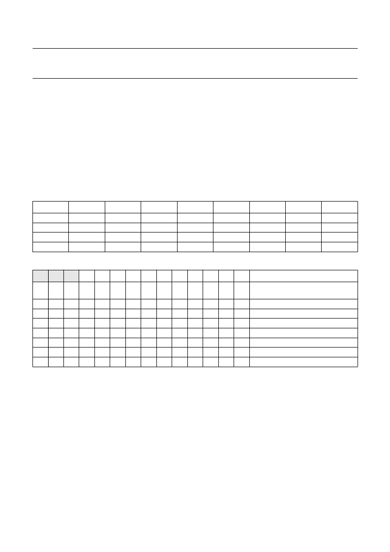
Table 37
Short instruction vector packet bit assignments
Table 38
Short instruction vector definitions
Note
1.
Assigned temporary address index a and associated frame number f (Section 8.8.4).
BYTE
BIT 7
BIT 6
BIT 5
BIT 4
BIT 3
BIT 2
BIT 1
BIT 0
3
2
1
0
0
e
x
d
4
WN
6
p
1
x
d
3
WN
5
p
0
d
10
d
2
WN
4
x
d
9
d
1
WN
3
x
d
8
d
0
WN
2
V
2
d
7
i
2
WN
1
V
1
d
6
i
1
WN
0
V
0
d
5
i
0
i
2
0
i
1
0
i
0
0
d
10
a
3
d
9
a
2
d
8
a
1
d
7
a
0
d
6
f
6
d
5
f
5
d
4
f
4
d
3
f
3
d
2
f
2
d
1
f
1
d
0
f
0
DESCRIPTION
temporary address assignment,
note 1
reserved
reserved
reserved
reserved
reserved
reserved
reserved for test
0
0
0
1
1
1
1
0
1
1
0
0
1
1
1
0
1
0
1
0
1
相關PDF資料 |
PDF描述 |
|---|---|
| PCD5008H | FLEX Pager Decoder |
| PCD5013 | FLEX roaming decoder II |
| PCD5013H | FLEX roaming decoder II |
| PCD5032 | ADPCM CODEC for digital cordless telephones |
| PCD5032H | ADPCM CODEC for digital cordless telephones |
相關代理商/技術參數 |
參數描述 |
|---|---|
| PCD5008H | 制造商:PHILIPS 制造商全稱:NXP Semiconductors 功能描述:FLEX Pager Decoder |
| PCD5008HBD-T | 制造商:未知廠家 制造商全稱:未知廠家 功能描述:Telecommunication Decoder |
| PCD5013 | 制造商:PHILIPS 制造商全稱:NXP Semiconductors 功能描述:FLEX roaming decoder II |
| PCD5013H | 制造商:PHILIPS 制造商全稱:NXP Semiconductors 功能描述:FLEX roaming decoder II |
| PCD5032 | 制造商:PHILIPS 制造商全稱:NXP Semiconductors 功能描述:ADPCM CODEC for digital cordless telephones |
發布緊急采購,3分鐘左右您將得到回復。