- 您現在的位置:買賣IC網 > PDF目錄98215 > TFP510PAP (TEXAS INSTRUMENTS INC) SPECIALTY CONSUMER CIRCUIT, PQFP64 PDF資料下載
參數資料
| 型號: | TFP510PAP |
| 廠商: | TEXAS INSTRUMENTS INC |
| 元件分類: | 消費家電 |
| 英文描述: | SPECIALTY CONSUMER CIRCUIT, PQFP64 |
| 封裝: | 10 X 10 MM, 1 MM HEIGHT, 0.50 MM PITCH, GREEN, PLASTIC, HTQFP-64 |
| 文件頁數: | 23/27頁 |
| 文件大小: | 383K |
| 代理商: | TFP510PAP |
第1頁第2頁第3頁第4頁第5頁第6頁第7頁第8頁第9頁第10頁第11頁第12頁第13頁第14頁第15頁第16頁第17頁第18頁第19頁第20頁第21頁第22頁當前第23頁第24頁第25頁第26頁第27頁
TFP510
TI PanelBus DIGITAL TRANSMITTER
SLDS146B JANUARY 2002 REVISED DECEMBER 2002
5
POST OFFICE BOX 655303
DALLAS, TEXAS 75265
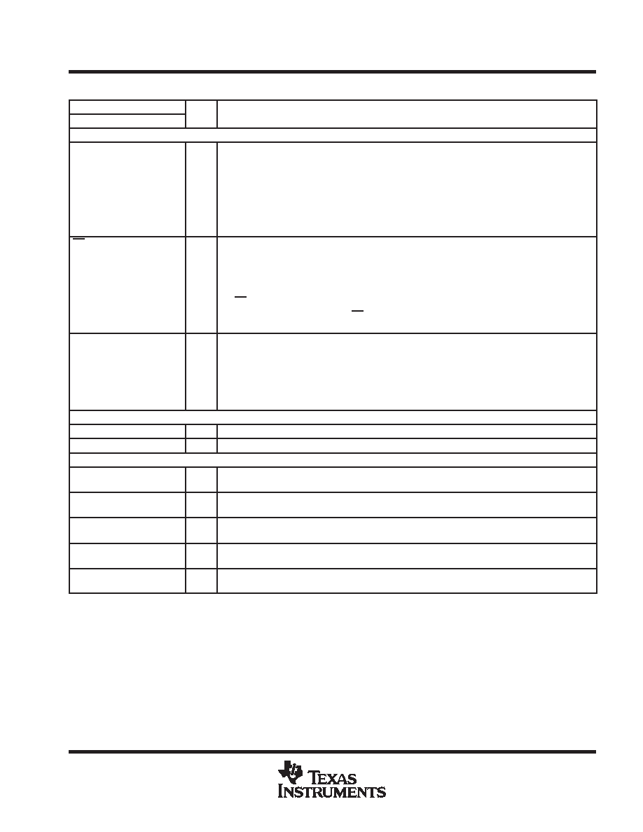
Terminal Functions (Continued)
TERMINAL
I/O
DESCRIPTION
NAME
NO.
I/O
DESCRIPTION
Configuration/Programming Pins (Continued)
MSEN
11
O
Monitor sense/programmable output 1. The operation of this pin depends on whether the I2C interface is
enabled or disabled. This pin has an open-drain output and is only 3.3-V tolerant. An external 5-k
pullup resistor connected to VDD is required on this pin.
When I2C is disabled (ISEL = low), a low level indicates a powered on receiver is detected at the
differential outputs. A high level indicates a powered-on receiver is not detected. This function is valid
only in dc-coupled systems.
When I2C is enabled (ISEL = high), this output is programmable through the I2C interface (see the I2C
register descriptions).
PD
10
I
Power down (active low). In the power-down state only the digital I/O buffers and I2C interface remain
active.
When I2C is disabled (ISEL = low), a high level selects the normal operating mode. A low level selects
the power-down mode.
When I2C is enabled (ISEL = high), the power-down state is selected through I2C. In this configuration,
the PD pin should be tied to GND.
Note: The default register value for PD is low, so the device is in power-down mode when I2C is first
enabled or after an I2C RESET.
VREF
3
I
Input reference voltage. Selects the swing range of the digital data inputs (DATA[23:0], DE, HSYNC,
VSYNC, and IDCK
±).
For high-swing 3.3-V input signal levels, VREF should be tied to VDD.
For low-swing input signal levels, VREF should be set to half of the maximum input voltage level. See the
recommended operating conditions section for the allowable range for VREF.
The desired VREF voltage level is typically derived using a simple voltage divider circuit.
Reserved
NC
49
I
No connection required. If connected, tie high.
RESERVED
34, 35
I
These pins are reserved and must be tied to GND for normal operation.
DVI Differential Signal Output Pins
TFADJ
19
I
Full-scale adjust. This pin controls the amplitude of the DVI output voltage swing, determined by the
value of the pullup resistor RTFADJ connected to TVDD.
TX0+
TX0
25
24
O
Channel-0 DVI differential output pair. TX0
± transmits the 8-bit blue pixel data during active video and
HSYNC and VSYNC during the blanking interval.
TX1+
TX1
28
27
O
Channel-1 DVI differential output pair. TX1
± transmits the 8-bit green pixel data during active video and
CTL[1] during the blanking interval.
TX2+
TX2
31
30
O
Channel-2 DVI differential output pair. TX2
± transmits the 8-bit red pixel data during active video and
CTL[3:2] during the blanking interval.
TXC+
TXC
22
21
O
DVI differential output clock.
相關PDF資料 |
PDF描述 |
|---|---|
| TFP513PAPG4 | SPECIALTY CONSUMER CIRCUIT, PQFP64 |
| TFP513PAP | SPECIALTY CONSUMER CIRCUIT, PQFP64 |
| TFP6422PAP | SPECIALTY CONSUMER CIRCUIT, PQFP64 |
| TFP6424PAP | SPECIALTY CONSUMER CIRCUIT, PQFP64 |
| TFP9431CPAP | SPECIALTY CONSUMER CIRCUIT, PQFP64 |
相關代理商/技術參數 |
參數描述 |
|---|---|
| TFP510PAPG4 | 制造商:Texas Instruments 功能描述:PNLBUS DGTL TRANSMITTER 64HTQFP - Rail/Tube |
| TFP513 | 制造商:TI 制造商全稱:Texas Instruments 功能描述:TI PANELBUS DIGITAL TRANSMITTER |
| TFP513PAP | 制造商:Texas Instruments 功能描述: |
| TFP513PAPG4 | 制造商:TI 制造商全稱:Texas Instruments 功能描述:TI PANELBUS DIGITAL TRANSMITTER |
| TFP5N60 | 制造商:TAK_CHEONG 制造商全稱:Tak Cheong Electronics (Holdings) Co.,Ltd 功能描述:N-Channel Power MOSFET 4.5A, 600V, 2.4Ω |
發布緊急采購,3分鐘左右您將得到回復。