- 您現(xiàn)在的位置:買賣IC網(wǎng) > PDF目錄98215 > TFP510PAP (TEXAS INSTRUMENTS INC) SPECIALTY CONSUMER CIRCUIT, PQFP64 PDF資料下載
參數(shù)資料
| 型號: | TFP510PAP |
| 廠商: | TEXAS INSTRUMENTS INC |
| 元件分類: | 消費(fèi)家電 |
| 英文描述: | SPECIALTY CONSUMER CIRCUIT, PQFP64 |
| 封裝: | 10 X 10 MM, 1 MM HEIGHT, 0.50 MM PITCH, GREEN, PLASTIC, HTQFP-64 |
| 文件頁數(shù): | 3/27頁 |
| 文件大小: | 383K |
| 代理商: | TFP510PAP |
第1頁第2頁當(dāng)前第3頁第4頁第5頁第6頁第7頁第8頁第9頁第10頁第11頁第12頁第13頁第14頁第15頁第16頁第17頁第18頁第19頁第20頁第21頁第22頁第23頁第24頁第25頁第26頁第27頁
TFP510
TI PanelBus DIGITAL TRANSMITTER
SLDS146B JANUARY 2002 REVISED DECEMBER 2002
11
POST OFFICE BOX 655303
DALLAS, TEXAS 75265
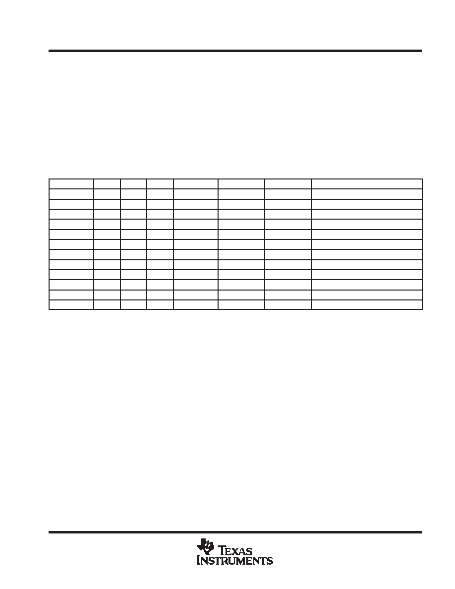
universal graphics controller interface modes
Table 1 is a tabular representation of the different modes for the universal graphics controller interface. The
12-bit mode is selected when BSEL = 0 and the 24-bit mode when BSEL = 1. The 12-bit mode uses dual-edge
clocking and the 24-bit mode uses single-edge clocking. The EDGE input is used to control the latching edge
in 24-bit mode, or the primary latching edge in 12-bit mode. When EDGE = 1, the data input is latched on the
rising edge of the input clock; and when EDGE = 0, the data input is latched on the falling edge of the input clock.
A fully differential input clock is available only in the low-swing mode. Single-ended clocking is not
recommended in the low-swing mode as this decreases common-mode noise rejection.
Note that BSEL, DSEL, and EDGE are determined by register CTL_1_MODE when I2C is enabled (ISEL = 1)
and by input pins when I2C is disabled (ISEL = 0).
Table 1. Universal Graphics Controller Interface Options (Tabular Representation)
VREF
BSEL
EDGE
DSEL
BUS WIDTH
LATCH MODE
CLOCK EDGE
CLOCK MODE
0.55 V 0.9 V
0
12-bit
Dual-edge
Falling
Differential (see Notes 9 and 10)
0.55 V 0.9 V
0
1
12-bit
Dual-edge
Falling
Single-ended
0.55 V – 0.9V
0
1
0
12-bit
Dual-edge
Rising
Differential (see Notes 9 and 10)
0.55 V 0.9 V
0
1
12-bit
Dual-edge
Rising
Single-ended
0.55 V – 0.9 V
1
0
24-bit
Single-edge
Falling
Single-ended
0.55 V – 0.9 V
1
0
1
24-bit
Single-edge
Falling
Differential (see Notes 9 and 11)
0.55 V – 0.9 V
1
0
24-bit
Single-edge
Rising
Single-ended
0.55 V – 0.9 V
1
24-bit
Single-edge
Rising
Differential (see Notes 9 and 11)
DVDD
0
X
12-bit
Dual-edge
Falling
Single-ended (see Note 12)
DVDD
0
1
X
12-bit
Dual-edge
Rising
Single-ended (see Note 12)
DVDD
1
0
X
24-bit
Single-edge
Falling
Single-ended (see Note 12)
DVDD
1
X
24-bit
Single-edge
Rising
Single-ended (see Note 12)
NOTES:
9. The differential clock input mode is only available in the low signal swing mode (i.e., VREF ≤ 0.9 V).
10. The TFP510 does not support a 12-bit dual-clock, single-edge input clocking mode.
11. The TFP510 does not support a 24-bit single-clock, dual-edge input clocking mode.
12. In the high-swing mode (VREF = DVDD), DSEL is a don’t care; therefore, the device is always in the single-ended latch mode.
相關(guān)PDF資料 |
PDF描述 |
|---|---|
| TFP513PAPG4 | SPECIALTY CONSUMER CIRCUIT, PQFP64 |
| TFP513PAP | SPECIALTY CONSUMER CIRCUIT, PQFP64 |
| TFP6422PAP | SPECIALTY CONSUMER CIRCUIT, PQFP64 |
| TFP6424PAP | SPECIALTY CONSUMER CIRCUIT, PQFP64 |
| TFP9431CPAP | SPECIALTY CONSUMER CIRCUIT, PQFP64 |
相關(guān)代理商/技術(shù)參數(shù) |
參數(shù)描述 |
|---|---|
| TFP510PAPG4 | 制造商:Texas Instruments 功能描述:PNLBUS DGTL TRANSMITTER 64HTQFP - Rail/Tube |
| TFP513 | 制造商:TI 制造商全稱:Texas Instruments 功能描述:TI PANELBUS DIGITAL TRANSMITTER |
| TFP513PAP | 制造商:Texas Instruments 功能描述: |
| TFP513PAPG4 | 制造商:TI 制造商全稱:Texas Instruments 功能描述:TI PANELBUS DIGITAL TRANSMITTER |
| TFP5N60 | 制造商:TAK_CHEONG 制造商全稱:Tak Cheong Electronics (Holdings) Co.,Ltd 功能描述:N-Channel Power MOSFET 4.5A, 600V, 2.4Ω |
發(fā)布緊急采購,3分鐘左右您將得到回復(fù)。