- 您現(xiàn)在的位置:買賣IC網(wǎng) > PDF目錄98271 > TPA2026D2YZHR (TEXAS INSTRUMENTS INC) AUDIO AMPLIFIER, PBGA16 PDF資料下載
參數(shù)資料
| 型號(hào): | TPA2026D2YZHR |
| 廠商: | TEXAS INSTRUMENTS INC |
| 元件分類: | 音頻/視頻放大 |
| 英文描述: | AUDIO AMPLIFIER, PBGA16 |
| 封裝: | 2.20 X 2.20 MM, GREEN, DSBGA-16 |
| 文件頁數(shù): | 27/39頁 |
| 文件大小: | 823K |
| 代理商: | TPA2026D2YZHR |
第1頁第2頁第3頁第4頁第5頁第6頁第7頁第8頁第9頁第10頁第11頁第12頁第13頁第14頁第15頁第16頁第17頁第18頁第19頁第20頁第21頁第22頁第23頁第24頁第25頁第26頁當(dāng)前第27頁第28頁第29頁第30頁第31頁第32頁第33頁第34頁第35頁第36頁第37頁第38頁第39頁
100°C/W
JA
DMAX
T
P
C
A
J
Max =
Max -
= 150 - 100 (0.4) = 110
q
°
Ferrite
ChipBead
Ferrite
ChipBead
1nF
OUTP
OUTN
www.ti.com
SLOS649A – MARCH 2010 – REVISED JANUARY 2011
EFFICIENCY AND THERMAL INFORMATION
The maximum ambient temperature depends on the heat-sinking ability of the PCB system. The derating factor
for the package is shown in the dissipation rating table. Converting this to qJA for the WCSP package:
(7)
Given qJA of 100°C/W, the maximum allowable junction temperature of 150°C, and the maximum internal
dissipation of 0.4 W (0.2 W per channel) for 1.5 W per channel, 8-
load, 5-V supply, from Figure 15, the
maximum ambient temperature can be calculated with the following equation.
(8)
Equation 8 shows that the calculated maximum ambient temperature is 110°C at maximum power dissipation
with a 5-V supply and 8-
a load. The TPA2026D2 is designed with thermal protection that turns the device off
when the junction temperature surpasses 150°C to prevent damage to the IC. Also, using speakers more
resistive than 8-
dramatically increases the thermal performance by reducing the output current and increasing
the efficiency of the amplifier.
OPERATION WITH DACS AND CODECS
In using Class-D amplifiers with CODECs and DACs, sometimes there is an increase in the output noise floor
from the audio amplifier. This occurs when output frequencies of the CODEC/DAC mix with the Class-D
switching frequency and create sum/difference components in the audio band. The noise increase can be solved
by placing an RC low-pass filter between the CODEC/DAC and audio amplifier. The filter reduces high
frequencies that cause the problem and allows proper performance.
SHORT CIRCUIT AUTO-RECOVERY
When a short circuit event happens, the TPA2026D2 goes to low duty cycle mode and tries to reactivate itself
every 110 s. This auto-recovery will continue until the short circuit event stops. This feature can protect the
device without affecting the device's long term reliability. FAULT bit (register 1, bit 3) still requires a write to clear.
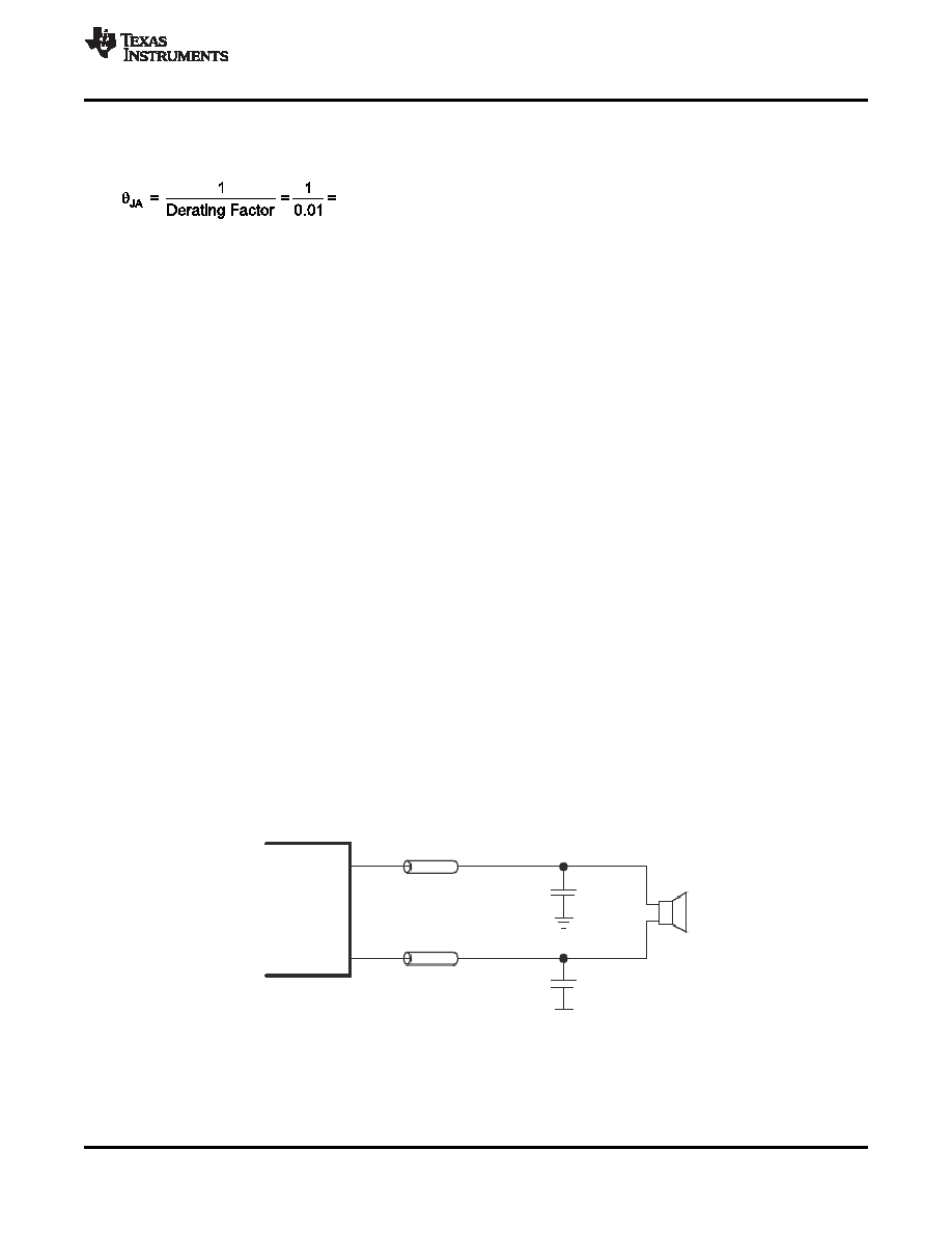
FILTER FREE OPERATION AND FERRITE BEAD FILTERS
A ferrite bead filter can often be used if the design is failing radiated emissions without an LC filter and the
frequency sensitive circuit is greater than 1 MHz. This filter functions well for circuits that just have to pass FCC
and CE because FCC and CE only test radiated emissions greater than 30 MHz. When choosing a ferrite bead,
choose one with high impedance at high frequencies, and low impedance at low frequencies. In addition, select a
ferrite bead with adequate current rating to prevent distortion of the output signal.
Use an LC output filter if there are low frequency (< 1 MHz) EMI sensitive circuits and/or there are long leads
from amplifier to speaker. Figure 48 shows typical ferrite bead and LC output filters.
Figure 48. Typical Ferrite Bead Filter (Chip bead example: TDK: MPZ1608S221A)
Copyright 2010–2011, Texas Instruments Incorporated
33
Product Folder Link(s): TPA2026D2
相關(guān)PDF資料 |
PDF描述 |
|---|---|
| TPA2026D2YZHT | AUDIO AMPLIFIER, PBGA16 |
| TPA2028D1YZFR | 3 W, 1 CHANNEL, AUDIO AMPLIFIER, PBGA9 |
| TPA2028D1YZFT | 3 W, 1 CHANNEL, AUDIO AMPLIFIER, PBGA9 |
| TPA2031D1YZFT | 2.5 W, 2 CHANNEL, AUDIO AMPLIFIER, BGA9 |
| TPA2031D1YZF | 2.5 W, 2 CHANNEL, AUDIO AMPLIFIER, BGA9 |
相關(guān)代理商/技術(shù)參數(shù) |
參數(shù)描述 |
|---|---|
| TPA2026D2YZHT | 功能描述:音頻放大器 3.2W/Ch Stereo Smart Gain Class-D Aud Amp RoHS:否 制造商:STMicroelectronics 產(chǎn)品:General Purpose Audio Amplifiers 輸出類型:Digital 輸出功率: THD + 噪聲: 工作電源電壓:3.3 V 電源電流: 最大功率耗散: 最大工作溫度: 安裝風(fēng)格:SMD/SMT 封裝 / 箱體:TQFP-64 封裝:Reel |
| TPA2028D1 | 制造商:TI 制造商全稱:Texas Instruments 功能描述:3-W Mono Class-D Audio Amplifier with Fast Gain Ramp SmartGain? AGC/DRC |
| TPA2028D1_10 | 制造商:TI 制造商全稱:Texas Instruments 功能描述:3-W Mono Class-D Audio Amplifier with Fast Gain Ramp SmartGaina?¢ AGC/DRC |
| TPA2028D1YZFEVM | 功能描述:音頻 IC 開發(fā)工具 TPA2028D1YZFEVM Eval Mod RoHS:否 制造商:Texas Instruments 產(chǎn)品:Evaluation Kits 類型:Audio Amplifiers 工具用于評(píng)估:TAS5614L 工作電源電壓:12 V to 38 V |
| TPA2028D1YZFEVM | 制造商:Texas Instruments 功能描述:DEVELOPMENT TOOL |
發(fā)布緊急采購,3分鐘左右您將得到回復(fù)。