- 您現(xiàn)在的位置:買賣IC網(wǎng) > PDF目錄98282 > TPS53851RHHT (TEXAS INSTRUMENTS INC) SWITCHING CONTROLLER, PQCC36 PDF資料下載
參數(shù)資料
| 型號(hào): | TPS53851RHHT |
| 廠商: | TEXAS INSTRUMENTS INC |
| 元件分類: | 穩(wěn)壓器 |
| 英文描述: | SWITCHING CONTROLLER, PQCC36 |
| 封裝: | PLASTIC, VQFN-36 |
| 文件頁(yè)數(shù): | 35/66頁(yè) |
| 文件大小: | 1264K |
| 代理商: | TPS53851RHHT |
第1頁(yè)第2頁(yè)第3頁(yè)第4頁(yè)第5頁(yè)第6頁(yè)第7頁(yè)第8頁(yè)第9頁(yè)第10頁(yè)第11頁(yè)第12頁(yè)第13頁(yè)第14頁(yè)第15頁(yè)第16頁(yè)第17頁(yè)第18頁(yè)第19頁(yè)第20頁(yè)第21頁(yè)第22頁(yè)第23頁(yè)第24頁(yè)第25頁(yè)第26頁(yè)第27頁(yè)第28頁(yè)第29頁(yè)第30頁(yè)第31頁(yè)第32頁(yè)第33頁(yè)第34頁(yè)當(dāng)前第35頁(yè)第36頁(yè)第37頁(yè)第38頁(yè)第39頁(yè)第40頁(yè)第41頁(yè)第42頁(yè)第43頁(yè)第44頁(yè)第45頁(yè)第46頁(yè)第47頁(yè)第48頁(yè)第49頁(yè)第50頁(yè)第51頁(yè)第52頁(yè)第53頁(yè)第54頁(yè)第55頁(yè)第56頁(yè)第57頁(yè)第58頁(yè)第59頁(yè)第60頁(yè)第61頁(yè)第62頁(yè)第63頁(yè)第64頁(yè)第65頁(yè)第66頁(yè)
M_CH1
M_CH2
S_CH1
S_CH2
NOT USED IN3PH
M
R
S
SLUS985 – DECEMBER 2009
www.ti.com
5.28.1 BASIC CONFIGURATIONS FOR 2, 4, 6, 8, 12 OR 16 PHASES
The solid square boxes in Figure 5-20 represent the PHSEL pin of the master (M) controller or a
numbered slave controller (S1-S7). The labels on the spokes of the wheels indicate a master Channel 1
and master Channel 2 (M_CH1 and M_CH2) and numbered slaves Channel 1 and slave Channel 2
(Sn_CH1 and Sn_CH2). The Channel 1 and Channel 2 of a given master or slave is always 180° out of
phase.
The master and slaves are automatically configured for proper phasing based on the resistor string from
the master to the slaves. All the resistors are 39 k
to 41.2 k. Part (A) above shows a single controller
operating two phases 180° out of phase. Part (B) above shows four phase operation. This is configured by
connecting a single resistor from the master PHSEL to GND and grounding the slave PHSEL pin. The
individual channels are 90° out of phase. Part (C) above shows six phase operation. This is configured by
connecting two resistors from the master PHSEL to GND. The first resistor tap is connected to slave2
PHSEL pin and then grounding the slave1 PHSEL pin. The individual channels are 60°out of phase. Part
(D) above shows eight phase operation. This is configured by connecting three resistors from the master
PHSEL to GND. The first resistor tap is connected to slave3 PHSEL pin. The second resistor tap is
connected to slave2 PHSEL pin and then grounding the slave1 PHSEL pin. The individual channels are
45° out of phase. Part (F) above shows twelve phase operation. This is configured by connecting two
resistors from the master PHSEL to GND. The master PHSEL pin is also connected to slave5 PHSEL pin.
The first resistor tap is connected to slave2 and slave4 PHSEL pins and then grounding the slave1 and
slave3 PHSEL pins. The individual channels are 30° out of phase. Additionally, the ILIM2 pins of slave5,
slave4 and slave3 are left open (internal pull-up) or externally connected to BP5. Part (G) above shows
sixteen phase operation. This is configured by connecting three resistors from the master PHSEL to GND.
The master PHSEL pin is also connected to slave7 PHSEL pin. The first resistor tap is connected to
slave3 and slave6 PHSEL pins. The second resistor tap is connected to slave2 and slave5 PHSEL pins
and then grounding the slave1 and slave4 PHSEL pins. The individual channels are 22.5° out of phase.
Additionally, the ILIM2 pins of slave7, slave6, slave5 and slave4 are left open (internal pull-up) or
externally connected to BP5.
5.28.2 CONFIGURING FOR OTHER NUMBER OF PHASES
Configuring for other than 2, 4, 6, 8, 12 or 16 phases is simply a matter of not attaching one or more slave
controllers. The phasing between master and populated slaves is as shown above. For example a
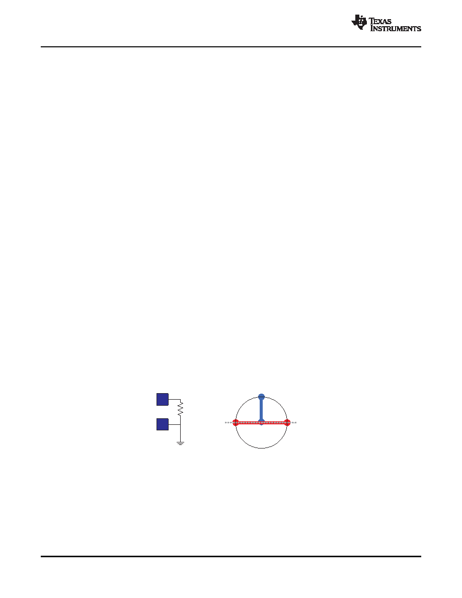
3-phase system could be configured with a master CH1 and master CH2 and 1 phase of a slave.
Referring to part (B) above, the 3 phases could be master CH1, master CH2 and slave CH1 or slave CH2
as shown in Figure 5-21.
Figure 5-21. Phase System: 2 Channels of the Master and 1 Channel of the Slave
The 3-phase system could also be configured with 1 channel of the master and 2 channels of the slave.
Referring to part (B) above, the 3 phases could be master CH1 or master CH2 and slave CH1 and slave
CH2. In either of these configurations there is 90° between two of the channels and 180° between the
other channel. The unused channel could be another independent output voltage whose clocking would
occupy the phase not used in the 3-phase system. This philosophy can be used for any number of phases
not shown in Figure 5-20, Clock Phasing Summary.
40
APPLICATION INFORMATION
Copyright 2009, Texas Instruments Incorporated
Product Folder Link(s): TPS53851
相關(guān)PDF資料 |
PDF描述 |
|---|---|
| TPS54010PWPG4 | 25 A SWITCHING REGULATOR, 762 kHz SWITCHING FREQ-MAX, PDSO28 |
| TPS54040DGQ | 0.5 A SWITCHING REGULATOR, 2500 kHz SWITCHING FREQ-MAX, PDSO10 |
| TPS54073PWPRG4 | 25 A SWITCHING REGULATOR, 762 kHz SWITCHING FREQ-MAX, PDSO28 |
| TPS54073PWPR | 25 A SWITCHING REGULATOR, 762 kHz SWITCHING FREQ-MAX, PDSO28 |
| TPS54073PWP | 25 A SWITCHING REGULATOR, 762 kHz SWITCHING FREQ-MAX, PDSO28 |
相關(guān)代理商/技術(shù)參數(shù) |
參數(shù)描述 |
|---|---|
| TPS53915EVM-587 | 功能描述:TPS53915 SWIFT?, D-CAP3?, Eco-Mode? DC/DC, Step Down 1, Non-Isolated Outputs Evaluation Board 制造商:texas instruments 系列:SWIFT?,D-CAP3?,Eco-Mode? 零件狀態(tài):有效 主要用途:DC/DC,步降 輸出和類型:1,非隔離 功率 - 輸出:- 電壓 - 輸出:1.2V 電流 - 輸出:12A 電壓 - 輸入:12V 穩(wěn)壓器拓?fù)?降壓 頻率 - 開(kāi)關(guān):- 板類型:完全填充 所含物品:板 使用的 IC/零件:TPS53915 標(biāo)準(zhǔn)包裝:1 |
| TPS53915RVET | 制造商:Texas Instruments 功能描述:1.5V TO 18V INPUT (4.5V TO 25V BIAS), 12-A SYNCHRONOUS STEP- - Tape and Reel 制造商:Texas Instruments 功能描述:IC REG BUCK SYNC ADJ 12A 28VQFN |
| TPS5401 | 制造商:TI 制造商全稱:Texas Instruments 功能描述:0.5-A, 42-V Input, Step-Down SWIFT? Converter |
| TPS54010 | 制造商:TI 制造商全稱:Texas Instruments 功能描述:SWIFT Converter Product Portfolio |
| TPS54010EVM-067 | 功能描述:電源管理IC開(kāi)發(fā)工具 4.0 Vin DC/DC Conv RoHS:否 制造商:Maxim Integrated 產(chǎn)品:Evaluation Kits 類型:Battery Management 工具用于評(píng)估:MAX17710GB 輸入電壓: 輸出電壓:1.8 V |
發(fā)布緊急采購(gòu),3分鐘左右您將得到回復(fù)。