- 您現在的位置:買賣IC網 > PDF目錄98282 > TPS54320RHLR (TEXAS INSTRUMENTS INC) SWITCHING REGULATOR, 1320 kHz SWITCHING FREQ-MAX, PQCC14 PDF資料下載
參數資料
| 型號: | TPS54320RHLR |
| 廠商: | TEXAS INSTRUMENTS INC |
| 元件分類: | 穩壓器 |
| 英文描述: | SWITCHING REGULATOR, 1320 kHz SWITCHING FREQ-MAX, PQCC14 |
| 封裝: | 3.50 X 3.50 MM, GREEN, PLASTIC, QFN-14 |
| 文件頁數: | 13/39頁 |
| 文件大小: | 1358K |
| 代理商: | TPS54320RHLR |
第1頁第2頁第3頁第4頁第5頁第6頁第7頁第8頁第9頁第10頁第11頁第12頁當前第13頁第14頁第15頁第16頁第17頁第18頁第19頁第20頁第21頁第22頁第23頁第24頁第25頁第26頁第27頁第28頁第29頁第30頁第31頁第32頁第33頁第34頁第35頁第36頁第37頁第38頁第39頁
Vref
VOUT
R8
R4
C4
C6
R9
Coea
Roea
gmea
COMP
VSENSE
Type 2A
Type 2B
R4
C4
C11
Type 3
ea
ps
2
c
VOUT
Co
R4 =
gm
Vref
gm
p
O
L
1
p =
C
R
2
÷
è
p
L
R
Co
C4 =
R4
ESR
R
Co
C6 =
R4
(
)
1
C11
2
R8 fc
=
× ×
×
p
SLVS982A – AUGUST 2010 – REVISED SEPTEMBER 2010
www.ti.com
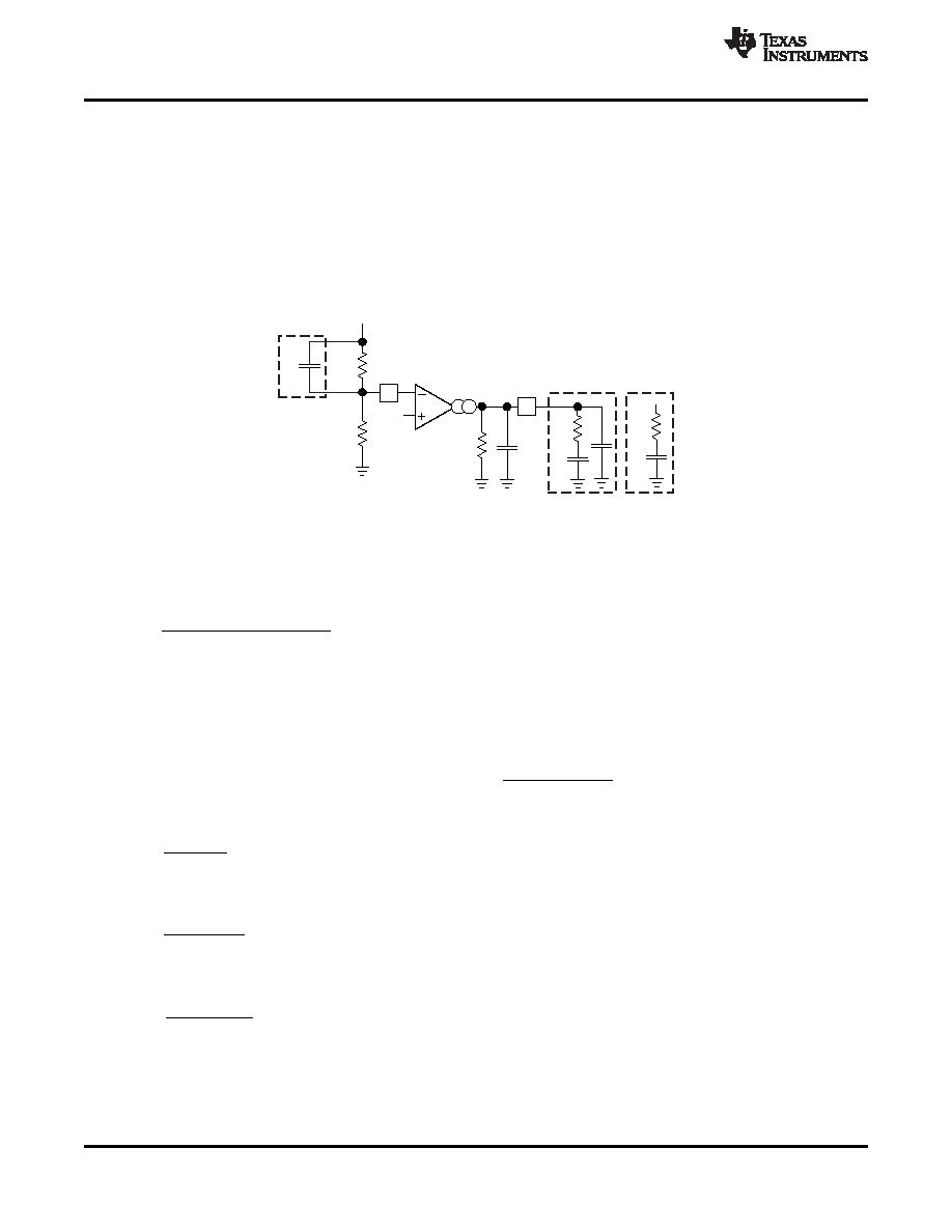
Small Signal Model for Frequency Compensation
The device uses a transconductance amplifier for the error amplifier and readily supports two of the commonly
used Type II compensation circuits and a Type III frequency compensation circuit, as shown in Figure 33. In
Type 2A, one additional high frequency pole, C6, is added to attenuate high frequency noise. In Type III, one
additional capacitor, C11, is added to provide a phase boost at the crossover frequency. See Designing Type III
Compensation for Current Mode Step-Down Converters (SLVA352) for a complete explanation of Type III
compensation.
The design guidelines below are provided for advanced users who prefer to compensate using the general
method. The below equations only apply to designs whose ESR zero is above the bandwidth of the control loop.
This is usually true with ceramic output capacitors.
Figure 33. Types of Frequency Compensation
The general design guidelines for device loop compensation are as follows:
1. Determine the crossover frequency, fc. A good starting point is 1/10th of the switching frequency, fsw.
2. R4 can be determined by:
(14)
Where:
gmea is the GM amplifier gain (1300mA/V)
gmps is the power stage gain (12A/V)
Vref is the reference voltage (0.8V)
3. Place a compensation zero at the dominant pole:
C4 can be determined by:
(15)
4. C6 is optional. It can be used to cancel the zero from the ESR (Equivalent Series Resistance) of the output
capacitor CO.
(16)
5. Type III compensation can be implemented with the addition of one capacitor, C11. This allows for slightly
higher loop bandwidths and higher phase margins. If used, C11 is calculated from Equation 17.
(17)
20
Copyright 2010, Texas Instruments Incorporated
Product Folder Link(s) :TPS54320
相關PDF資料 |
PDF描述 |
|---|---|
| TPS54320RHL | SWITCHING REGULATOR, PQCC14 |
| TPS54327DDAR | 5.7 A SWITCHING REGULATOR, 700 kHz SWITCHING FREQ-MAX, PDSO8 |
| TPS54328DDA | 5.7 A SWITCHING REGULATOR, 700 kHz SWITCHING FREQ-MAX, PDSO8 |
| TPS54328DDAR | 5.7 A SWITCHING REGULATOR, 700 kHz SWITCHING FREQ-MAX, PDSO8 |
| TPS54331DG4 | 2 A SWITCHING REGULATOR, 684 kHz SWITCHING FREQ-MAX, PDSO8 |
相關代理商/技術參數 |
參數描述 |
|---|---|
| TPS54320RHLT | 功能描述:直流/直流開關調節器 4.5-17V Inp3A Sync Step Down Cnvrtr RoHS:否 制造商:International Rectifier 最大輸入電壓:21 V 開關頻率:1.5 MHz 輸出電壓:0.5 V to 0.86 V 輸出電流:4 A 輸出端數量: 最大工作溫度: 安裝風格:SMD/SMT 封裝 / 箱體:PQFN 4 x 5 |
| TPS54320RHLT | 制造商:Texas Instruments 功能描述:IC SYNC STEP-DOWN CONTROLLER 1.2MHZ Q 制造商:Texas Instruments 功能描述:IC, SYNC STEP-DOWN CONTROLLER, 1.2MHZ, QFN-14 |
| TPS54325 | 制造商:TI 制造商全稱:Texas Instruments 功能描述:4.5-V to 18-V, 3-A OUTPUT SYNCHRONOUS STEP DOWN SWITCHER WITH INTEGRATED FET (SWIFT?) |
| TPS54325_10 | 制造商:TI 制造商全稱:Texas Instruments 功能描述:4.5-V to 18-V, 3-A OUTPUT SYNCHRONOUS STEP DOWN SWITCHER WITH INTEGRATED FET (SWIFT?) |
| TPS54325EVM | 功能描述:電源管理IC開發工具 5-17V Input 3A SWIFT CVTR Eval RoHS:否 制造商:Maxim Integrated 產品:Evaluation Kits 類型:Battery Management 工具用于評估:MAX17710GB 輸入電壓: 輸出電壓:1.8 V |
發布緊急采購,3分鐘左右您將得到回復。