- 您現在的位置:買賣IC網 > PDF目錄382685 > TRF5001GQE RECEIVER|BICMOS|BGA|80PIN|PLASTIC PDF資料下載
參數資料
| 型號: | TRF5001GQE |
| 英文描述: | RECEIVER|BICMOS|BGA|80PIN|PLASTIC |
| 中文描述: | 接收機| BICMOS工藝| BGA封裝| 80腳|塑料 |
| 文件頁數: | 11/19頁 |
| 文件大小: | 258K |
| 代理商: | TRF5001GQE |
SLWS084 – DECEMBER 2000
11
POST OFFICE BOX 655303
DALLAS, TEXAS 75265
PRINCIPLES OF OPERATION
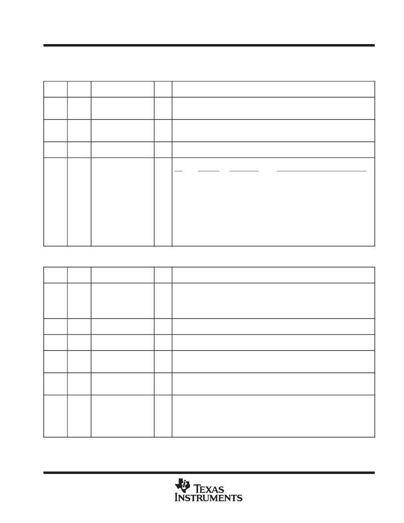
Table 1. Serial Word 0 Format
DATA
FIELD
WORD
PARAMETER
BITS
DESCRIPTION/CONDITIONS
DS
0
DEEPSLEEP
1
Deep sleep:
1 = enabled
0 = disabled
BS
0
ENABLANK
1
Enable blanking sleep mode:
1 = enabled
0 = disabled
RD
0
REFDIVNUM
12
Reference frequency division ratio; typical value is 420 (TCXO frequency is
16.8 MHz).
CF
0
COMPFREQ
4
Comparison frequency select:
bits
CF (kHz)
0000
20
0001
30
0010
40
0011
60
0101
120
1000
20
1001
30
1010
40
1011
60
1101
120
1111
240
Main Divider
11274
7516
5637
3758
1879
no change
no change
no change
no change
no change
no change
Division ratio for clock LPF tuning loop
2
3
4 (default)
6
12
2
3
4
6
12
24
Table 2. Serial Word 1 Format
DATA
FIELD
WORD
PARAMETER
BITS
DESCRIPTION/CONDITIONS
SP
1
SETP
4
This 4-bit word is used as a reference by the AGC control loop. SETP is used for
AGC fine gain tuning. Initial value is 3 (0011). This value assures that the AGC
control loop sets the rms value at the ADC input equal to 1/4 of the ADC range.
Increasing the value (or decreasing) by 1 or 2 steps results in an equivalent number
of steps increasing (or decreasing) the AGC gain setting.
AG
1
GAINSPI
4
This 4-bit word sets the AGC gain (0–15). Each step increases amplifier gain by
3 dB.
O
1
OVERRIDE
1
When this bit is set to 1, AGC gain is overridden using GAINSPI word. When this bit
is reset to 0, AGC gain is set by the control loop.
H
1
HOLD
1
Hold AGC gain setting:
1 = enabled
0 = disabled
CS
1
ADREFSW
1
ADC clock select:
1 = internal
0 = external
RS
1
REFDIVSEL
2
Select the division ratio (12 or 24) to generate the internal ADC clock from the
second LO:
00 = ADC_clk equals Ref_Freq (only for testing)
01 = divide by 12
10 = divide by 24
11 = no ADC clock
P
相關PDF資料 |
PDF描述 |
|---|---|
| TRICARD7014 | CHIP CARD |
| TRIDENTMONITORLIMAVGA | LCD MONITOR |
| TRIKC023D-8018-2 | "DISPLAY KIT COLOUR LCD 4.7""" |
| TRIKC023D-8046-2 | "DISPLAY KIT COLOUR LCD 6""" |
| TRIKT013D8089-2 | COLOUR TFT LCD KIT |
相關代理商/技術參數 |
參數描述 |
|---|---|
| TRF5011BN-LF001 | 制造商:Opnext 功能描述:XFP FORM FACTOR - Trays |
| TRF5011FN-LF001 | 制造商:Opnext 功能描述:XFP FORM FACTOR - Trays |
| TRF5015FN-GA000 | 制造商:Opnext 功能描述:XFP, 10GBASE-LR - Boxed Product (Development Kits) |
| TRF5015FN-PA000 | 制造商:Opnext 功能描述:TRF5015FN-PA000 - Trays |
| TRF5015FN-PA610 | 制造商:Opnext 功能描述:TRF5015FN-PA610 - Trays |
發布緊急采購,3分鐘左右您將得到回復。