- 您現在的位置:買賣IC網 > PDF目錄382685 > TRF5001GQE RECEIVER|BICMOS|BGA|80PIN|PLASTIC PDF資料下載
參數資料
| 型號: | TRF5001GQE |
| 英文描述: | RECEIVER|BICMOS|BGA|80PIN|PLASTIC |
| 中文描述: | 接收機| BICMOS工藝| BGA封裝| 80腳|塑料 |
| 文件頁數: | 7/19頁 |
| 文件大小: | 258K |
| 代理商: | TRF5001GQE |
SLWS084 – DECEMBER 2000
7
POST OFFICE BOX 655303
DALLAS, TEXAS 75265
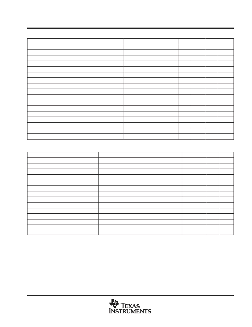
IF strip
PARAMETER
TEST CONDITIONS
MIN
TYP
MAX
UNIT
Frequency range
100
222.54
250
MHz
Noise figure
At maximum gain setting
8
12
dB
Input 1-dB compression point
Gain = 37
Gain SPI = 0
–53
dBVrms
dBVrms
dBVrms
dBVrms
dBVrms
dBVrms
dB
Input third-order intercept point
Gain = 37
Gain SPI = 0
–43
Input 1-dB compression point
Gain = 73
Gain SPI = 12
–84
Input third-order intercept point
Gain = 73
Gain SPI = 12
–74
Input 1-dB compression point
Gain = 82
Gain SPI = 15
–93
Input third-order intercept point
Gain = 82
Gain SPI = 15
–83
IF strip gain range
Typical
37
73
82
AGC range
In 3-dB steps
45
±
1
4.0
dB
Gain error (linearity)
In any 20-dB window
±
1.5
dB
3-dB corner frequency
MHz
dB
μ
s/step
μ
s/step
Input impedance
Differential
200
Input return loss
With external match
10
AGC attack time
For a one gain step of 3 dB
50
AGC decay time
For a one gain step of 3 dB
50
Interface
3-wire interface
analog-to-digital converter (see Notes 4 and 5)
PARAMETER
TEST CONDITIONS
MIN
TYP
MAX
UNIT
Resolution (number of bits)
4
bits
Sample rate
6
18.79
20
MHz
k
MHz
Input impedance
Differential, fin = 2.87 MHz
1
Input bandwidth
6
Input dc offset voltage (offset error)
–1/4
1/4
LSB
Input differential nonlinearity (DNL error)
–1/4
1/4
LSB
Input integral nonlinearity (INL error)
–1/4
1/4
LSB
RMS signal-to-noise
Sampling rate = 18.79 MHz, input tone = 2.94 MHz
23.6
dB
Signal-to-noise plus distortion (SINAD)
Sampling rate = 18.79 MHz, input tone = 2.94 MHz
22.8
dB
Effective number of bits (ENOB)
Sampling rate = 18.79 MHz, input tone = 2.87 MHz
3.57
bits
Total harmonic distortion (THD)
Sampling rate = 18.79 MHz, input tone = 2.87 MHz
–31
dBc
Capacitance output load drive capability
Capacitance
5
10
pF
Data output latch
1
Clock
cycle
NOTES:
3. No missing codes.
4. ADC data words are sequential (i.e., Vin = Vin_ADC_min = 0000, . . . , Vin = Vin_ADC_max = 1111)
5. Data format of the 4-bit ADC is unsigned binary.
P
相關PDF資料 |
PDF描述 |
|---|---|
| TRICARD7014 | CHIP CARD |
| TRIDENTMONITORLIMAVGA | LCD MONITOR |
| TRIKC023D-8018-2 | "DISPLAY KIT COLOUR LCD 4.7""" |
| TRIKC023D-8046-2 | "DISPLAY KIT COLOUR LCD 6""" |
| TRIKT013D8089-2 | COLOUR TFT LCD KIT |
相關代理商/技術參數 |
參數描述 |
|---|---|
| TRF5011BN-LF001 | 制造商:Opnext 功能描述:XFP FORM FACTOR - Trays |
| TRF5011FN-LF001 | 制造商:Opnext 功能描述:XFP FORM FACTOR - Trays |
| TRF5015FN-GA000 | 制造商:Opnext 功能描述:XFP, 10GBASE-LR - Boxed Product (Development Kits) |
| TRF5015FN-PA000 | 制造商:Opnext 功能描述:TRF5015FN-PA000 - Trays |
| TRF5015FN-PA610 | 制造商:Opnext 功能描述:TRF5015FN-PA610 - Trays |
發布緊急采購,3分鐘左右您將得到回復。