- 您現在的位置:買賣IC網 > PDF目錄382685 > TRF5001GQE RECEIVER|BICMOS|BGA|80PIN|PLASTIC PDF資料下載
參數資料
| 型號: | TRF5001GQE |
| 英文描述: | RECEIVER|BICMOS|BGA|80PIN|PLASTIC |
| 中文描述: | 接收機| BICMOS工藝| BGA封裝| 80腳|塑料 |
| 文件頁數: | 12/19頁 |
| 文件大小: | 258K |
| 代理商: | TRF5001GQE |

DATE AND TRACKING INFORMATION
12
POST OFFICE BOX 655303
DALLAS, TEXAS 75265
PRINCIPLES OF OPERATION
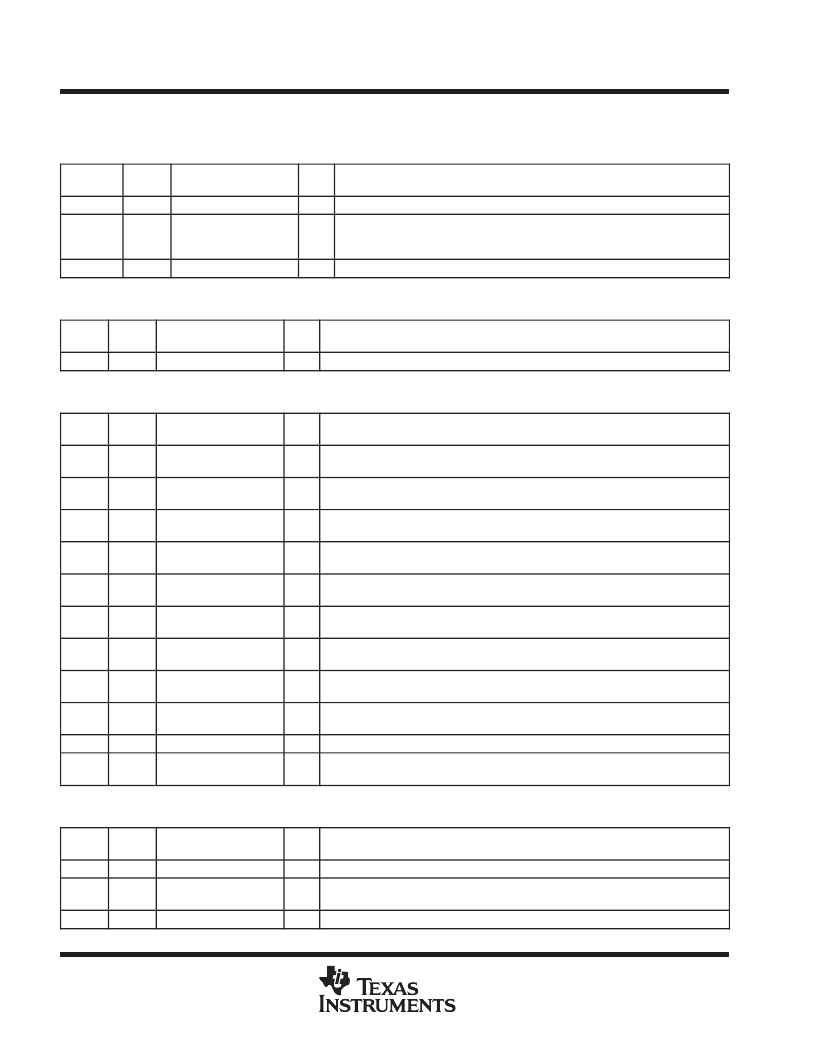
Table 3. Serial Word 2 Format (Spare Register)
BIT
POSITION
WORD
PARAMETER
BITS
DESCRIPTION/CONDITIONS
17–14
2
SWCAPSET
1
4-bit word, used in VCO version 3, to control 4 switch cap. Default value = 1000.
13
2
DIS_VARAC_BUF
1
In VCO versions 2 and 3, this bit disables the voltage buffer at VARACIN.
1 = buffer is enabled (default)
0 = buffer is disabled
9
2
MIX_BIAS_SEL
1
This bit is used to select the bias of the RF mixer. Default is 0.
Table 4. Serial Word 4 Format
DATA
FIELD
WORD
PARAMETER
BITS
DESCRIPTION/CONDITIONS
MD
4
MAINDEVNUM
15
Main divider ratio. Initial value is 5637.
Table 5. Serial Word 5 Format
DATA
FIELD
WORD
PARAMETER
BITS
DESCRIPTION/CONDITIONS
EL
5
LNAENA
1
1 = enable LNA
0 = disable LNA
EM
5
MIX1ENA
1
1 = enable RF mixer
0 = disable RF mixer
EV
5
VCOENA
1
1 = enable VCO
0 = disable VCO
ES
5
ENASYN
1
1 = enable synthesizer
0 = disable synthesizer
EA
5
ENAAGCAMP
1
1 = enable AGC amplifier
0 = disable AGC amplifier
EI
5
MIX2ENA
1
1 = enable IF mixer
0 = disable IF mixer
EF
5
FILTENA
1
1 = enable LFP
0 = disable LFP
EB
5
IFAMPENA
1
1 = enable IF amplifier
0 = disable IF amplifier
EA
5
ADCENA
1
1 = enable ADC
0 = disable ADC
LR
5
LPFRESET
1
The 0-to-1 transition restarts LPF tuning
AS
5
AGCSEL
1
1 = fast AGC control loop
0 = slow fast AGC control loop (default)
Table 6. Serial Word 6 Format
DATA
FIELD
WORD
PARAMETER
BITS
DESCRIPTION/CONDITIONS
CV
6
COMPAREVAL
9
9-bit word used as a comparing frequency during LPF tuning. Initial value = 400.
LE
6
LEVELTEST_EN
1
1 = enable digital output test
0 = disable digital output test
LD
6
LEVEL_DATA
1
Sets level for digital output test.
P
相關PDF資料 |
PDF描述 |
|---|---|
| TRICARD7014 | CHIP CARD |
| TRIDENTMONITORLIMAVGA | LCD MONITOR |
| TRIKC023D-8018-2 | "DISPLAY KIT COLOUR LCD 4.7""" |
| TRIKC023D-8046-2 | "DISPLAY KIT COLOUR LCD 6""" |
| TRIKT013D8089-2 | COLOUR TFT LCD KIT |
相關代理商/技術參數 |
參數描述 |
|---|---|
| TRF5011BN-LF001 | 制造商:Opnext 功能描述:XFP FORM FACTOR - Trays |
| TRF5011FN-LF001 | 制造商:Opnext 功能描述:XFP FORM FACTOR - Trays |
| TRF5015FN-GA000 | 制造商:Opnext 功能描述:XFP, 10GBASE-LR - Boxed Product (Development Kits) |
| TRF5015FN-PA000 | 制造商:Opnext 功能描述:TRF5015FN-PA000 - Trays |
| TRF5015FN-PA610 | 制造商:Opnext 功能描述:TRF5015FN-PA610 - Trays |
發布緊急采購,3分鐘左右您將得到回復。