- 您現在的位置:買賣IC網 > PDF目錄365968 > TSB43LV81 IC CYCLONE III FPGA 10K 144 EQFP PDF資料下載
參數資料
| 型號: | TSB43LV81 |
| 英文描述: | IC CYCLONE III FPGA 10K 144 EQFP |
| 中文描述: | 總線控制器 |
| 文件頁數: | 3/159頁 |
| 文件大小: | 1085K |
| 代理商: | TSB43LV81 |
第1頁第2頁當前第3頁第4頁第5頁第6頁第7頁第8頁第9頁第10頁第11頁第12頁第13頁第14頁第15頁第16頁第17頁第18頁第19頁第20頁第21頁第22頁第23頁第24頁第25頁第26頁第27頁第28頁第29頁第30頁第31頁第32頁第33頁第34頁第35頁第36頁第37頁第38頁第39頁第40頁第41頁第42頁第43頁第44頁第45頁第46頁第47頁第48頁第49頁第50頁第51頁第52頁第53頁第54頁第55頁第56頁第57頁第58頁第59頁第60頁第61頁第62頁第63頁第64頁第65頁第66頁第67頁第68頁第69頁第70頁第71頁第72頁第73頁第74頁第75頁第76頁第77頁第78頁第79頁第80頁第81頁第82頁第83頁第84頁第85頁第86頁第87頁第88頁第89頁第90頁第91頁第92頁第93頁第94頁第95頁第96頁第97頁第98頁第99頁第100頁第101頁第102頁第103頁第104頁第105頁第106頁第107頁第108頁第109頁第110頁第111頁第112頁第113頁第114頁第115頁第116頁第117頁第118頁第119頁第120頁第121頁第122頁第123頁第124頁第125頁第126頁第127頁第128頁第129頁第130頁第131頁第132頁第133頁第134頁第135頁第136頁第137頁第138頁第139頁第140頁第141頁第142頁第143頁第144頁第145頁第146頁第147頁第148頁第149頁第150頁第151頁第152頁第153頁第154頁第155頁第156頁第157頁第158頁第159頁
TSB43LV81
IEEE-1394 LINK-LAYER CONTROLLER/400M-PHY ONE-CHIP
Page 3
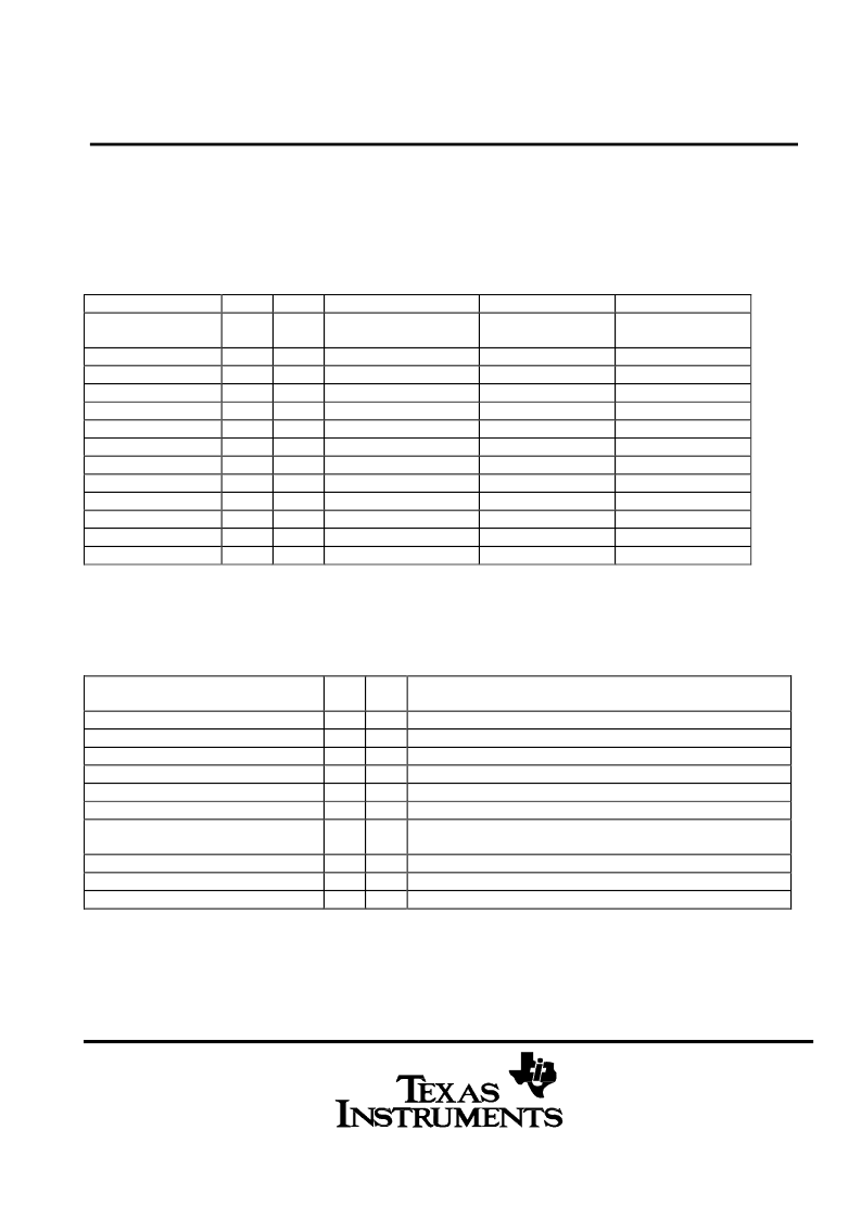
1.3.
Terminal Functions
1.3.1.
AUX PIN USAGE vs. MODE[1:0]
The Signals in the AUX vs. MODE are defined as follows:
Both internal LINK and PHY work on NORMAL mode. Only PHY functions on PHY-Mode. Link functions under
LINK-Mode.
MODE[1:0]
0 0
NAME
PIN
I/O
NORMAL
0 1
1 0
PHY-MODE
(only PHY active)
CTL0
CTL1
D0
D1
D2
D3
D4
D5
D6
D7
LREQ
SCLK
LINK-MODE
(only Link active)
D7
D6
D5
D4
D3
D2
D1
D0
CTL1
CTL0
SCLK
LREQ
AUX[0] (
Note-2
)
AUX[1] (
Note-2
)
AUX[2] (
Note-2
)
AUX[3] (
Note-2
)
AUX[4] (
Note-2
)
AUX[5] (
Note-2
)
AUX[6] (
Note-2
)
AUX[7] (
Note-2
)
AUX[8] (
Note-2
)
AUX[9] (
Note-2
)
AUX[10] (
Note-2
)
AUX[11] (
Note-2
)
Note-1) AUX[8:10] input mean PowerClass [2:0], Internal PHY read this value at Power Up Reset. (input)
Note-2) These input has BUS holder circuit for isolation by cap.
1
2
4
6
8
9
I/O
I/O
I/O
I/O
I/O
I/O
I/O
I/O
I/O
I/O
I
O
HiZ
HiZ
HiZ
HiZ
HiZ
HiZ
HiZ
HiZ
11
12
13
15
17
18
Powerclass/CycleIn (Note-1)
Powerclass/CycleIn (Note-1)
Powerclass/CycleIn (Note-1)
OPEN (pull down)
1.3.2.
MicroController/MicroProcessor Interface Definition
The Signals in the MicroController/MicroProcessor Interface are defined as follows:
NAME
PIN
I/O
DESCRIPTION
XCS
ALE
XRD
XWR
XINT
XWAIT
ADDR[7:0]
110
109
106
107
79
105
-
I
I
I
I
I/O
O
I/O
Chip select.
Address Latch En. Ignored when not DA mux mode.
Read cycle Enable.
Write cycle Enable.
Interrupt
Wait.
Address
(DA[7:0] for 8bits mode, BDIO[15:8] for 16bits parallel mode)
Data (DA [15:8] for 8bits mode DA[15:0] for 16bit mode)
Bit width select. Set HI is 16bit mode.
Mode selects. Set HI is Data Address multiplex mode.
DATA[15:0]
M8M16
MUXMODE
-
I/O
I
I
30
33
相關PDF資料 |
PDF描述 |
|---|---|
| TSB43AA22PDT | IC ARRIA GX FPGA 50K 484FBGA |
| TSB43AA82A | IC ARRIA GX FPGA 50K 780FBGA |
| TSB43AB21A | IC ARRIA GX FPGA 60K 484FBGA |
| TSB43AB21A-EP | IC ARRIA GX FPGA 60K 1152FBGA |
| TSB43AA82I | 1394 INTEGRATED PHY AND LINK LAYER CONTROLLER |
相關代理商/技術參數 |
參數描述 |
|---|---|
| TSB4559D10-2 | 制造商:Thomas & Betts 功能描述:TRANS CONN 4 POS 500-10 COMPACT DES |
| TSB4559J10C | 制造商:Thomas & Betts 功能描述:4 POS TRANS STUD CONN 500 W/COV |
| TSB5 | 制造商:未知廠家 制造商全稱:未知廠家 功能描述:EURO TERMINAL BLOCKS |
| TSB5000131DS | 制造商:TE Connectivity 功能描述: |
| TSB5000231 | 制造商:TE Connectivity 功能描述: |
發布緊急采購,3分鐘左右您將得到回復。