- 您現在的位置:買賣IC網 > PDF目錄382706 > U6220B 1.3 GHz PLL for TV- and VCR- Tuner PDF資料下載
參數資料
| 型號: | U6220B |
| 英文描述: | 1.3 GHz PLL for TV- and VCR- Tuner |
| 中文描述: | 1.3千兆赫PLL的電視和錄像機,調諧器 |
| 文件頁數: | 9/14頁 |
| 文件大小: | 188K |
| 代理商: | U6220B |
U6220B
Preliminary Information
TELEFUNKEN Semiconductors
Rev. A2, 23-Sep-96
9 (14)
I
2
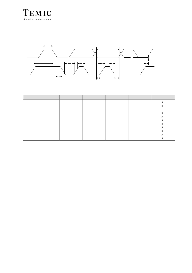
C Bus Description (continued)
I
2
C Bus Timing
SDA
SCL
t
t
t
t
t
t
t
t
t
t
R
F
S STP
H DAT
S DAT
HIGH
LOW
S STT
W STT
H STT
START
CLOCK
DATACHANGE
STOP
12429
Parameter
Symbol
tR
tF
FSCL
tHIGH
tLOW
tH STT
tW STT
tS STT
tS STP
tS DAT
tH DAT
Conditions
Min.
Max.
15
15
100
Unit
Rise time SDA, SCL
Fall time SDA, SCL
Clock frequency SCL
Clock ‘H’ pulse
Clock ‘L’ pulse
Hold time start
Waiting time start
Setup time start
Setup time stop
Setup time data
Hold time data
0
4
4
4
4
4
4
0.3
0
s
s
kHz
s
s
s
s
s
s
s
s
3-Wire Bus Description
When the U6220B is controlled via a 3-wire bus format,
then data, clock and enable signals are fed into the SDA,
SCL and AS/ENA lines respectively. The diagram
‘3-WIRE BUS PULSE DIAGRAM’ shows the data
format. The data consist of a single word, which contains
the programmable divider (14bit) and switch information
(4 bit). The data is only clocked into the internal data shift
register on the negative clock transition during the enable
high period. During enable low periods, the clock input
is disabled. New data words are only accepted by the
internal data latches from the shift register on a negative
transition of the enable signal, if exactly eighteen clock
pulses were sent during the high period of the enable. The
data sequence and the timing is described in the following
diagrams.
In 3-wire bus mode Pin 9 becomes automatically the
lock-signal output. an improved lock detect circuit
generates a flag when the loop has attained lock. ‘In lock’
is indicated by a low impedance state (on) of the open
collector output.
In 3-wire bus mode, the high charge pump current is
always. Only in I
2
C bus mode can the charge pump
current be controlled.
The complete PLL function can be disabled by
programming a division ratio of zero, which is normally
not used. This enables the tuner alignment by supplying
the tuning voltage directly through the 33-V supply
voltage of the tuner.
In 3-wire bus mode the division ratio of the reference
divider is fixed to divide by 512. It can be controlled only
in I
2
C bus mode.
相關PDF資料 |
PDF描述 |
|---|---|
| U6223B-AFP | Low power quad operational amplifier |
| U6223B-FP | Low power dual operational amplifier |
| U6224B-AFP | Low power dual operational amplifier |
| U6225B-AFP | Low power dual operational amplifier |
| U6225B | 2.9 GHz PLL for SAT TV Receiver with Universal Bus |
相關代理商/技術參數 |
參數描述 |
|---|---|
| U6220B-APG3 | 制造商:未知廠家 制造商全稱:未知廠家 功能描述:Analog IC |
| U6223B-AFP | 制造商:未知廠家 制造商全稱:未知廠家 功能描述:Analog IC |
| U6223B-FP | 制造商:未知廠家 制造商全稱:未知廠家 功能描述:Analog IC |
| U6224B-AFP | 制造商:未知廠家 制造商全稱:未知廠家 功能描述:Analog IC |
| U62256 | 制造商:未知廠家 制造商全稱:未知廠家 功能描述:STANDARD 32K X 8 SRAM |
發布緊急采購,3分鐘左右您將得到回復。