- 您現在的位置:買賣IC網 > PDF目錄373972 > AD9957_07 (Analog Devices, Inc.) 1 GSPS Quadrature Digital Upconverter with 18-Bit IQ Data Path and 14-Bit DAC PDF資料下載
參數資料
| 型號: | AD9957_07 |
| 廠商: | Analog Devices, Inc. |
| 英文描述: | 1 GSPS Quadrature Digital Upconverter with 18-Bit IQ Data Path and 14-Bit DAC |
| 中文描述: | 1 GSPS的正交數字上變頻器與18位智商數據路徑和14位DAC |
| 文件頁數: | 22/60頁 |
| 文件大小: | 840K |
| 代理商: | AD9957_07 |
第1頁第2頁第3頁第4頁第5頁第6頁第7頁第8頁第9頁第10頁第11頁第12頁第13頁第14頁第15頁第16頁第17頁第18頁第19頁第20頁第21頁當前第22頁第23頁第24頁第25頁第26頁第27頁第28頁第29頁第30頁第31頁第32頁第33頁第34頁第35頁第36頁第37頁第38頁第39頁第40頁第41頁第42頁第43頁第44頁第45頁第46頁第47頁第48頁第49頁第50頁第51頁第52頁第53頁第54頁第55頁第56頁第57頁第58頁第59頁第60頁
AD9957
Encoding and pulse shaping of symbols must be implemented
before the data is presented to the input of the AD9957. Data
delivered to the input of the AD9957 may be formatted as either
twos complement or offset binary (see the data format bit in
Table 13). In BFI mode, the bit sequence order can be set to
either MSB-first or LSB-first (via the Blackfin bit order bit).
Rev. 0 | Page 22 of 60
INVERSE CCI FILTER
The inverse cascaded comb integrator (CCI) filter predistorts
the data, compensating for the slight attenuation gradient imposed
by the CCI filter (see the Programmable Interpolating Filter
section). Data entering the first half-band filter occupies a maxi-
mum bandwidth of f
IQ
as defined by Nyquist (where f
IQ
is the
sample rate at the input of the first half-band filter); see Figure 33.
If the CCI filter is used, the inband attenuation gradient can pose a
problem for applications requiring an extremely flat pass band.
For example, if the spectrum of the data supplied to the AD9957
occupies a significant portion of the f
DATA
region, the higher
frequencies of the data spectrum are slightly more attenuated
than the lower frequencies (the worst-case overall droop from f
= 0 to f
DATA
is < 0.8 dB). The inverse CCI filter has a response
characteristic that is the inverse of the CCI filter response over
the f
IQ
region.
INBAND
ATTENUATION
GRADIENT
CIC FILTER RESPONSE
f
IQ
f
IQ
4
f
IQ
f
0
Figure 33. CCI Filter Response
The product of the two responses yields an extremely flat
pass band (±0.05 dB over the baseband Nyquist bandwidth)
eliminating the inband attenuation gradient introduced by the
CCI filter. The cost is a slight attenuation of the input signal
(approximately 0.5 dB for a CCI interpolation rate of 2, and
0.8 dB for higher interpolation rates).
The inverse CCI filter can be bypassed using the appropriate bit
in the register map; it is automatically bypassed if the CCI inter-
polation rate is 1×. When bypassed, power to the stage turns off
to reduce power consumption.
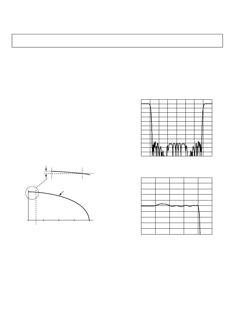
FIXED INTERPOLATOR (4×)
This block is a fixed 4× rate interpolator, implemented as a
cascade of two half-band filters. Together, the sampling rate
of these two filters increase by a factor of four while preserving
the spectrum of the baseband signal applied at the input. Both
are linear phase filters; virtually no phase distortion is intro-
duced within their pass bands. Their combined insertion loss
is 0.01 dB, preserving the relative amplitude of the input signal.
The filters are designed to deliver a composite performance that
yields a usable pass band of 40% of the input sample rate. Within
that pass band, ripple does not exceed 0.002 dB peak-to-peak.
The stop band extends from 60% to 340% of the input sample
rate and offers a minimum of 85 dB attenuation. Figure 34 and
Figure 35 show the composite response of the two half-band filters.
10
–120
–110
–100
–90
–80
–70
–60
–50
–40
–30
–20
–10
0
0
0.5
1.0
1.5
2.0
f
I
2.5
3.0
3.5
4.0
0
(
Figure 34. Half-Band 1 and Half-Band 2 Composite Response
(Frequency Scaled to Input Sample Rate of Half-Band 1)
–0.010
–0.008
0.008
–0.006
0.006
–0.004
0.004
–0.002
0.002
0
0.010
0
0.1
0.2
0.3
0.4
0.5
0
(
f
I
Figure 35. Composite Pass-Band Detail
(Frequency Scaled to Input Sample Rate of Half-Band 1)
In BFI mode, there are two additional half-band filters resident
yielding a total fixed interpolation factor of 16×. The extra BFI
filters use the same filter tap coefficient values as the QDUC
half-band filters, but their data pathway is 16 bits (instead of 18
bits as with the QDUC half-band filters). As such, baseband
quantization noise is higher in BFI mode.
Knowledge of the frequency response of the half-band filters is
essential to understanding their impact on the spectral properties
of the input signal. This is especially true when using the quad-
rature modulator to upconvert a baseband signal containing
complex data symbols that have been pulse shaped.
相關PDF資料 |
PDF描述 |
|---|---|
| AD9958BCPZ-REEL7 | 2-Channel 500 MSPS DDS with 10-Bit DACs |
| AD9958 | 2-Channel 500 MSPS DDS with 10-Bit DACs |
| AD9958BCPZ | 2-Channel 500 MSPS DDS with 10-Bit DACs |
| AD9970 | 14-Bit CCD Signal Processor with Precision Timing Generator |
| AD9971 | 12-Bit CCD Signal Processor with Precision Timing |
相關代理商/技術參數 |
參數描述 |
|---|---|
| AD9957BCPZ | 制造商:Analog Devices 功能描述:GSPS QUADRATURE DIGITAL UPCONVERTER W/18-BIT IQ DATA PATH - Trays |
| AD9957BSVZ | 功能描述:IC DDS 1GSPS 14BIT IQ 100TQFP RoHS:是 類別:集成電路 (IC) >> 接口 - 直接數字合成 (DDS) 系列:- 產品變化通告:Product Discontinuance 27/Oct/2011 標準包裝:2,500 系列:- 分辨率(位):10 b 主 fclk:25MHz 調節字寬(位):32 b 電源電壓:2.97 V ~ 5.5 V 工作溫度:-40°C ~ 85°C 安裝類型:表面貼裝 封裝/外殼:16-TSSOP(0.173",4.40mm 寬) 供應商設備封裝:16-TSSOP 包裝:帶卷 (TR) |
| AD9957BSVZ-REEL | 功能描述:IC DDS 1GSPS 14BIT IQ 100TQFP RoHS:是 類別:集成電路 (IC) >> 接口 - 直接數字合成 (DDS) 系列:- 產品變化通告:Product Discontinuance 27/Oct/2011 標準包裝:2,500 系列:- 分辨率(位):10 b 主 fclk:25MHz 調節字寬(位):32 b 電源電壓:2.97 V ~ 5.5 V 工作溫度:-40°C ~ 85°C 安裝類型:表面貼裝 封裝/外殼:16-TSSOP(0.173",4.40mm 寬) 供應商設備封裝:16-TSSOP 包裝:帶卷 (TR) |
| AD9957BSVZREEL13 | 制造商:AD 制造商全稱:Analog Devices 功能描述:1 GSPS Quadrature Digital Upconverter w/18-Bit IQ Data Path and 14-Bit DAC |
| AD9958 | 制造商:AD 制造商全稱:Analog Devices 功能描述:2-Channel 500 MSPS DDS with 10-Bit DACs |
發布緊急采購,3分鐘左右您將得到回復。