- 您現在的位置:買賣IC網 > Datasheet目錄39 > ADM1027ARQZ-RL7 (ON Semiconductor)IC REMOTE THERMAL CTLR 24QSOP Datasheet資料下載
參數資料
| 型號: | ADM1027ARQZ-RL7 |
| 廠商: | ON Semiconductor |
| 文件頁數: | 19/56頁 |
| 文件大小: | 1822K |
| 描述: | IC REMOTE THERMAL CTLR 24QSOP |
| 產品變化通告: | MFG CHG Notification ADI to ON Semi Product Discontinuation Notice 25/Aug/2008 Product Obsolescence 30/Sept/2009 |
| 標準包裝: | 1,000 |
| 系列: | dBCool® |
| 功能: | 風扇控制,溫度監控器 |
| 傳感器類型: | 內部和外部 |
| 感應溫度: | 0°C ~ 105°C,外部傳感器 |
| 精確度: | ±1°C |
| 拓撲: | ADC,比較器,風扇速度計數器,多路復用器,寄存器庫 |
| 輸出類型: | SMBus? |
| 輸出警報: | 無 |
| 輸出風扇: | 是 |
| 電源電壓: | 3 V ~ 5.5 V |
| 工作溫度: | 0°C ~ 105°C |
| 安裝類型: | 表面貼裝 |
| 封裝/外殼: | 24-SSOP(0.154",3.90mm 寬) |
| 供應商設備封裝: | 24-QSOP |
| 包裝: | 帶卷 (TR) |
第1頁第2頁第3頁第4頁第5頁第6頁第7頁第8頁第9頁第10頁第11頁第12頁第13頁第14頁第15頁第16頁第17頁第18頁當前第19頁第20頁第21頁第22頁第23頁第24頁第25頁第26頁第27頁第28頁第29頁第30頁第31頁第32頁第33頁第34頁第35頁第36頁第37頁第38頁第39頁第40頁第41頁第42頁第43頁第44頁第45頁第46頁第47頁第48頁第49頁第50頁第51頁第52頁第53頁第54頁第55頁第56頁
REV. A
ADM1027
19
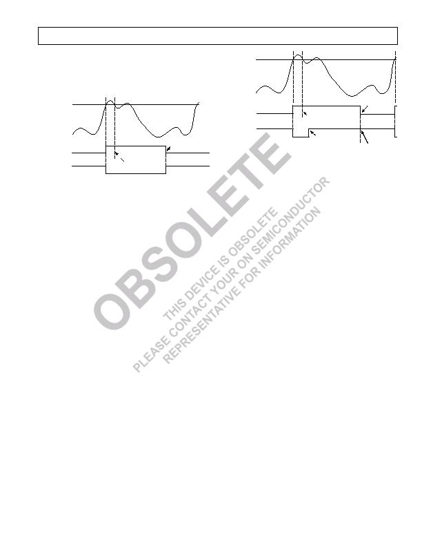
SMBALERT INTERRUPT BEHAVIOR
The ADM1027 can be polled for status, or an SMBALERT
interrupt can be generated for out-of-limit conditions. It is
important to note how the SMBALERT output and status bits
behave when writing interrupt handler software.
STICKY
STATUS
BIT
HIGH LIMIT
TEMPERATURE
SMBALERT
CLEARED ON READ
(TEMP BELOW LIMIT)
TEMP BACK IN LIMIT
(STATUS BIT STAYS SET)
Figure 16. SMBALERT and Status Bit Behavior
Figure 16 shows how the SMBALERT output and sticky status
bits behave. Once a limit is exceeded, the corresponding status
bit is set to 1. The status bit remains set until the error condition
subsides and the status register is read. The status bits are referred
to as sticky since they remain set until read by software. This
ensures that an out-of-limit event cannot be missed if software
is polling the device periodically. Note that the SMBALERT
output remains low for the entire duration that a reading is
out-of-limit and until the status register has been read. This has
implications on how software handles the interrupt.
HANDLING SMBALERT INTERRUPTS
To prevent the system from being tied up servicing interrupts,
it is recommend to handle the SMBALERT interrupt as follows:
1. Detect the SMBALERT assertion.
2. Enter the interrupt handler.
3. Read the status registers to identify the interrupt source.
4. Mask the interrupt source by setting the appropriate mask bit
in the interrupt mask registers (Reg. 0x74, 0x75).
5. Take the appropriate action for a given interrupt source.
6. Exit the interrupt handler.
7. Periodically poll the status registers. If the interrupt status bit
has cleared, reset the corresponding interrupt mask bit to 0.
This will cause the SMBALERT output and status bits to
behave as shown in Figure 17.
STICKY
STATUS
BIT
HIGH LIMIT
TEMPERATURE
SMBALERT
CLEARED ON READ
(TEMP BELOW LIMIT)
TEMP BACK IN LIMIT
(STATUS BIT STAYS SET)
INTERRUPT
MASK BIT SET
INTERRUPT MASK
BIT CLEARED
(SMBALERT REARMED)
Figure 17. How Masking the Interrupt Source
Affects SMBALERT Output
MASKING INTERRUPT SOURCES
Interrupt Mask Registers 1 and 2 are located at Addresses 0x74
and 0x75. These allow individual interrupt sources to be masked
out to prevent SMBALERT interrupts. Note that masking an
interrupt source prevents only the SMBALERT output from
being asserted; the appropriate status bit will be set as normal.
INTERRUPT MASK REGISTER 1 (REG. 0x74)
Bit 7 (OOL) = 1, set this bit to 1 to allow masking of interrupts
by Status Register 2. If this bit = 0, then setting a bit in Mask
Register 2 to 1 will have no effect.
Bit 6 (R2T) = 1, masks SMBALERT for Remote 2 temperature.
Bit 5 (LT) = 1, masks SMBALERT for local temperature.
Bit 4 (R1T) = 1, masks SMBALERT for Remote 1 temperature.
Bit 3 (5 V) = 1, masks SMBALERT for 5 V channel.
Bit 2 (V
CC
) = 1, masks SMBALERT for V
CC
channel.
Bit 1 (V
CCP
) = 1, masks SMBALERT for V
CCP
channel.
Bit 0 (2.5 V) = 1, masks SMBALERT for 2.5 V channel.
INTERRUPT MASK REGISTER 2 (REG. 0x75)
Bit 7 (D2) = 1, masks SMBALERT for Diode 2 errors.
Bit 6 (D1) = 1, masks SMBALERT for Diode 1 errors.
Bit 5 (FAN4) = 1, masks SMBALERT for Fan 4.
Bit 4 (FAN3) = 1, masks SMBALERT for Fan 3.
Bit 3 (FAN2) = 1, masks SMBALERT for Fan 2.
Bit 2 (FAN1) = 1, masks SMBALERT for Fan 1.
Bit 1 (OVT) = 1, masks SMBALERT for overtemperature
(exceeding THERM limits).
Bit 0 (12 V) = 1, masks SMBALERT for 12 V channel.
Rev. 3 | Page 19 of 56 | www.onsemi.com
相關PDF資料 |
PDF描述 |
|---|---|
| ADM1029ARQZ-R7 | IC SENSOR 2TEMP/FAN CTRL 24QSOP |
| ADM1030ARQZ-RL7 | IC SNSR TEMP/FAN PWM CTRL 16QSOP |
| ADM1032ARZ-REEL | IC TEMP MONITOR 85DEG 8SOIC |
| ADM1033ARQZ-RL7 | IC THERM/FAN SPEED CTLR 16-QSOP |
| ADM1034ARQZ-REEL | IC THERM/FAN SPEED CTRLR 16-QSOP |
相關代理商/技術參數 |
參數描述 |
|---|---|
| ADM1027ARQZ-RL71 | 制造商:ONSEMI 制造商全稱:ON Semiconductor 功能描述:dBCOOLa?¢ Remote Thermal Controller and Voltage Monitor |
| ADM1028 | 制造商:AD 制造商全稱:Analog Devices 功能描述:Remote Thermal Diode Monitor with Linear Fan Control |
| ADM1028ARQ | 功能描述:IC SENSOR TEMP/FAN CTRL 16QSOP RoHS:否 類別:集成電路 (IC) >> PMIC - 熱管理 系列:- 標準包裝:1 系列:- 功能:溫度監控系統(傳感器) 傳感器類型:內部和外部 感應溫度:-40°C ~ 125°C,外部傳感器 精確度:±2.5°C 本地(最大值),±5°C 遠程(最大值) 拓撲:ADC,比較器,寄存器庫 輸出類型:2 線 SMBus? 輸出警報:無 輸出風扇:無 電源電壓:2.7 V ~ 5.5 V 工作溫度:-40°C ~ 125°C 安裝類型:表面貼裝 封裝/外殼:SOT-23-8 供應商設備封裝:SOT-23-8 包裝:Digi-Reel® 其它名稱:296-22675-6 |
| ADM1028ARQ-REEL7 | 制造商:Rochester Electronics LLC 功能描述:TDM + LINEAR FAN CONTROL I.C. - Tape and Reel |
| ADM1029 | 制造商:AD 制造商全稱:Analog Devices 功能描述:Dual PWM Fan Controller and Temperature Monitor for High Availability Systems |
發布緊急采購,3分鐘左右您將得到回復。