- 您現在的位置:買賣IC網 > Datasheet目錄39 > ADM1034ARQZ-REEL (ON Semiconductor)IC THERM/FAN SPEED CTRLR 16-QSOP Datasheet資料下載
參數資料
| 型號: | ADM1034ARQZ-REEL |
| 廠商: | ON Semiconductor |
| 文件頁數: | 12/38頁 |
| 文件大小: | 427K |
| 描述: | IC THERM/FAN SPEED CTRLR 16-QSOP |
| 產品變化通告: | MFG CHG Notification ADI to ON Semi |
| 標準包裝: | 2,500 |
| 功能: | 風扇控制,溫度監控器 |
| 傳感器類型: | 內部和外部 |
| 感應溫度: | -40°C ~ 125°C,外部傳感器 |
| 精確度: | ±1°C |
| 拓撲: | ADC,比較器,多路復用器,寄存器庫 |
| 輸出類型: | SMBus? |
| 輸出警報: | 是 |
| 輸出風扇: | 是 |
| 電源電壓: | 3 V ~ 5.5 V |
| 工作溫度: | -40°C ~ 125°C |
| 安裝類型: | 表面貼裝 |
| 封裝/外殼: | 16-SSOP(0.154",3.90mm 寬) |
| 供應商設備封裝: | 16-QSOP |
| 包裝: | 帶卷 (TR) |
第1頁第2頁第3頁第4頁第5頁第6頁第7頁第8頁第9頁第10頁第11頁當前第12頁第13頁第14頁第15頁第16頁第17頁第18頁第19頁第20頁第21頁第22頁第23頁第24頁第25頁第26頁第27頁第28頁第29頁第30頁第31頁第32頁第33頁第34頁第35頁第36頁第37頁第38頁
ADM1034
http://onsemi.com
12
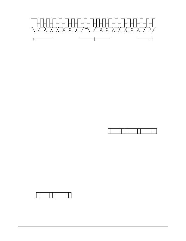
Figure 19. Reading Data from a Previously Selected Register
SCL
SDA
D7
D6
D5
D4
D3
D2
D1
D0
NO ACK. BY
ADM1034
START BY
MASTER
9
1
ACK. BY
ADM1034
9
STOP BY
MASTER
A2
A1
A0
1
FRAME 1
SERIAL BUS ADDRESS BYTE
FRAME 2
DATA BYTE FROM ADM1034
R/W
A3
A4
A5
A6
Register Addresses for Single/Block Byte Modes
The ADM1034 supports single byte as well as block read
and write operations. The register address determines
whether a single byte or multiple byte (block) operation is
run. For a single byte operation, the MSB of the register
address is set to 0; for a multiple byte operation, it is set to 1.
The number of bytes read in a multiple byte operation is set
in the #Bytes/Block Read Register at Address 0x00. The
number of bytes written to the ADM1034 is specified during
the block write operation. The addresses quoted in the
register map and throughout this data sheet assume single
byte operation. For multiple byte operations, set the MSB of
each register address to 1.
Write Operations
The SMBus specifications define protocols for read and
write operations. The ADM1034 supports send byte, write
byte, and block byte SMBus write protocols. The following
abbreviations are used in the diagrams:
S START
P STOP
R READ
W WRITE
A ACKNOWLEDGE
A
NO ACKNOWLEDGE
Send Byte
In this operation, the master device sends a
single-command byte to a slave device as follows:
1. The master device asserts a start condition on
SDA.
2. The master sends a 7-bit address followed by the
write bit (low).
3. The addressed slave device asserts ACK on SDA.
4. The master sends the register address.
5. The slave asserts ACK on SDA.
6. The master asserts a stop condition on SDA, and
the transaction ends.
Figure 20. Send Byte
SLAVE
ADDRESS
S
REG
ADDRESS
W
A
A
P
The ADM1034 uses the send byte operation to write a
register address to the APR for a subsequent read from the
same address. (See Figure 24). The user may be required to
read data from the register immediately after setting up the
address. If so, the master can assert a repeat start condition
immediately after the final ACK and carry out a single byte
read without asserting an intermediate stop condition.
Write Byte
In this operation, the master device sends a register
address and one data byte to the slave device as follows:
1. The master asserts a start condition on SDA.
2. The master sends the 7-bit slave address followed
by a write bit (low).
3. The addressed slave device asserts ACK on SDA.
4. The master sends the register address. The MSB of
the register address should equal 0 for a write byte
operation. If the MSB equals 1, a block write
operation takes place.
5. The slave asserts ACK on SDA.
6. The master sends a data byte.
7. The slave asserts ACK on SDA.
8. The master asserts a stop condition on SDA to end
the transaction.
Figure 21. Write Byte Operation
SLAVE
ADDRESS
S
REG
ADDRESS
DATA
W
A
A
A
P
Block Write
In this operation, the master device writes a block of data
to a slave address as follows. A maximum of 32 bytes can be
written.
1. The master asserts a start condition on SDA.
2. The master sends the 7-bit slave address followed
by a write bit (low).
3. The addressed slave device asserts ACK on SDA.
4. The master sends the register address. The register
address sets up the address pointer register and
determines whether a block write (MSB = 1) or a
byte write (MSB = 0) takes place.
5. The slave asserts ACK on SDA.
6. The master sends the byte count.
7. The slave asserts ACK on SDA.
8. The master sends N data bytes.
9. The slave asserts ACK on SDA after each byte.
10. The master asserts a stop condition on SDA to end
the transaction.
相關PDF資料 |
PDF描述 |
|---|---|
| ADN8810ACPZ-REEL7 | IC CURRENT SOURCE(12BIT) 24LFCSP |
| ADP2140ACPZ3328R7 | IC REG DL BCK/LINEAR 10LFCSP |
| ADP5022ACBZ-6-R7 | IC REG TRPL BCK/LINEAR 16WLCSP |
| ADP5041ACPZ-1-R7 | IC REG TRPL BCK/LINEAR 20-LFCSP |
| ADP5042ACPZ-2-R7 | IC REG TRPL BCK/LINEAR 20LFCSP |
相關代理商/技術參數 |
參數描述 |
|---|---|
| ADM1034ARQZ-REEL7 | 功能描述:IC THERM/FAN SPEED CTRLR 16-QSOP RoHS:是 類別:集成電路 (IC) >> PMIC - 熱管理 系列:- 標準包裝:1 系列:- 功能:溫度監控系統(傳感器) 傳感器類型:內部和外部 感應溫度:-40°C ~ 125°C,外部傳感器 精確度:±2.5°C 本地(最大值),±5°C 遠程(最大值) 拓撲:ADC,比較器,寄存器庫 輸出類型:2 線 SMBus? 輸出警報:無 輸出風扇:無 電源電壓:2.7 V ~ 5.5 V 工作溫度:-40°C ~ 125°C 安裝類型:表面貼裝 封裝/外殼:SOT-23-8 供應商設備封裝:SOT-23-8 包裝:Digi-Reel® 其它名稱:296-22675-6 |
| ADM1040 | 制造商:AD 制造商全稱:Analog Devices 功能描述:Power Supply Monitor ASIC |
| ADM1041 | 制造商:AD 制造商全稱:Analog Devices 功能描述:Secondary-Side Controller with Current Share and Housekeeping |
| ADM1041A | 制造商:AD 制造商全稱:Analog Devices 功能描述:Secondary-Side Controller with Current Share and Housekeeping |
| ADM1041AARQZ | 功能描述:IC SECONDARY SIDE CTRLR 24QSOP RoHS:是 類別:集成電路 (IC) >> PMIC - 電源控制器,監視器 系列:- 產品培訓模塊:Lead (SnPb) Finish for COTS Obsolescence Mitigation Program 標準包裝:2,500 系列:- 應用:多相控制器 輸入電壓:- 電源電壓:9 V ~ 14 V 電流 - 電源:- 工作溫度:-40°C ~ 85°C 安裝類型:表面貼裝 封裝/外殼:40-WFQFN 裸露焊盤 供應商設備封裝:40-TQFN-EP(5x5) 包裝:帶卷 (TR) |
發布緊急采購,3分鐘左右您將得到回復。