- 您現在的位置:買賣IC網 > Datasheet目錄39 > ADM1034ARQZ-REEL (ON Semiconductor)IC THERM/FAN SPEED CTRLR 16-QSOP Datasheet資料下載
參數資料
| 型號: | ADM1034ARQZ-REEL |
| 廠商: | ON Semiconductor |
| 文件頁數: | 18/38頁 |
| 文件大小: | 427K |
| 描述: | IC THERM/FAN SPEED CTRLR 16-QSOP |
| 產品變化通告: | MFG CHG Notification ADI to ON Semi |
| 標準包裝: | 2,500 |
| 功能: | 風扇控制,溫度監控器 |
| 傳感器類型: | 內部和外部 |
| 感應溫度: | -40°C ~ 125°C,外部傳感器 |
| 精確度: | ±1°C |
| 拓撲: | ADC,比較器,多路復用器,寄存器庫 |
| 輸出類型: | SMBus? |
| 輸出警報: | 是 |
| 輸出風扇: | 是 |
| 電源電壓: | 3 V ~ 5.5 V |
| 工作溫度: | -40°C ~ 125°C |
| 安裝類型: | 表面貼裝 |
| 封裝/外殼: | 16-SSOP(0.154",3.90mm 寬) |
| 供應商設備封裝: | 16-QSOP |
| 包裝: | 帶卷 (TR) |
第1頁第2頁第3頁第4頁第5頁第6頁第7頁第8頁第9頁第10頁第11頁第12頁第13頁第14頁第15頁第16頁第17頁當前第18頁第19頁第20頁第21頁第22頁第23頁第24頁第25頁第26頁第27頁第28頁第29頁第30頁第31頁第32頁第33頁第34頁第35頁第36頁第37頁第38頁
ADM1034
http://onsemi.com
18
Table 17. INTERRUPT STATUS REGISTER 1
(REG. 0X4F)
Bit #
Name
Description
7
LH
1 = Local high temperature limit has been
exceeded.
6
LL
1 = Local low temperature limit has been
exceeded.
5
R1H
1 = Remote 1 high temperature limit has
been exceeded.
4
R1L
1 = Remote 1 low temperature limit has
been exceeded.
3
R1D
1 = Remote 1 diode error; indicates an
open or short on the D1+/D1 pins.
2
R2H
1 = Remote 2 high temperature limit has
been exceeded.
1
R2L
1 = Remote 2 low temperature limit has
been exceeded.
0
R2D
1 = Remote 2 diode error; indicates an
open or short on the D2+/D2 pins.
Table 18. STATUS REGISTER 2 (REG. 0X50)
Bit #
Name
Description
7
LT
1 = Local THERM
temperature limit has
been exceeded.
6
R1T
1 = Remote 1 THERM
temperature limit
has been exceeded.
5
R2T
1 = Remote 2 THERM
temperature limit
has been exceeded.
4
T%
1 = THERM
% ontime limit has been
exceeded.
3
TA
1 = One of the THERM
limits has been
exceeded; and the THERM
output signal
has been asserted.
2
TS
1 = THERM
state. Indicates the THERM
pin is active; clears on a read if THERM
is not active. Does not generate an
ALERT
in ALERT
comp mode.
1
Res
Reserved
0
Res
Reserved
Table 19. STATUS REGISTER 3 (REG. 0X51)
Bit #
Name
Description
7
F1S
1 = Fan 1 has stalled.
6
FA
1 = Fan alarm speed. Fan1 and Fan 2
are running at alarm speed.
5
F2S
1 = Fan 2 has stalled.
4
Res
Reserved
3
Res
Reserved
2
Res
Reserved
1
Res
Reserved
0
ALERT
1 = ALERT
low; indicates the ALERT
line has been pulled low.
ALERT
Interrupt Behavior
The ADM1034 generates an ALERT
whenever an
out-of-limit measurement is made (if it is not masked out).
The user can also detect out-of-limit conditions by polling
the ADM1034 status registers. It is important to note how
the SMBus ALERT
output behaves when writing interrupt
handler software.
The ALERT
output on the ADM1034 can be programmed
to operate in either SMBusALERT
mode or in comp mode.
In SMBusALERT
mode, the ALERT
output remains low
until the measurement falls back within its programmed
limits and either the status register is read or an ARA is
completed. In comp mode, the ALERT
output automatically
resets once the temperature measurement falls back within
the programmed limits.
Configuring the ALERT
Output
For SMBusALERT
mode, set the ALERT
configuration bit
(Bit 3) of the Configuration Register 1 (Address 0x01) to 0.
In SMBusALERT
mode, a status bit is set when a
measurement goes outside of its programmed limit. If the
corresponding mask bit is not set, the ALERT
output is
pulled low. If the measured value falls back within the limits,
the ALERT
output remains low until the corresponding
status register is read or until an ARA is completed (as long
as no other measurement is outside its limits).
For comp mode, set the ALERT
configuration bit (Bit 3)
of Configuration Register 1 (Address 0x01) to1.
In comp mode, the ALERT
output is automatically pulled
low when a measurement goes outside its programmed limits.
Once the measurement falls back within its limits (and
assuming no other measurement channel is outside its limits),
the ALERT
output is automatically pulled high again.
The main difference between the two modes is that the
SMBusALERT
does not reset without software intervention,
whereas the comp mode ALERT
output automatically resets.
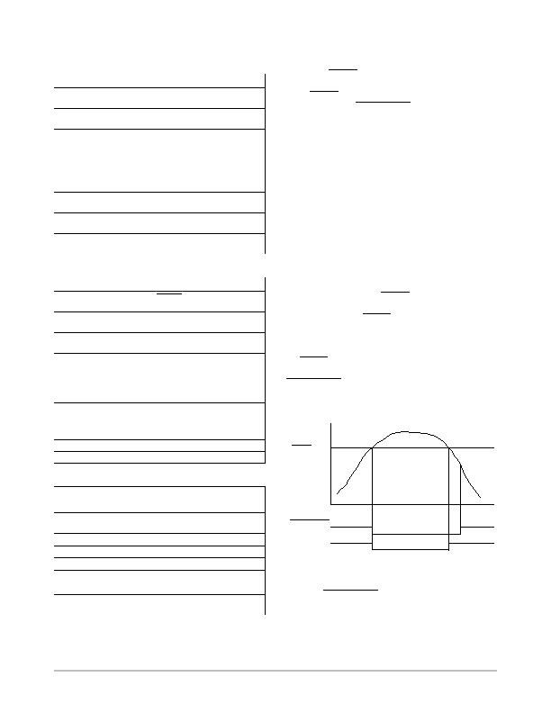
Figure 30. ALERT
Comparator and SMBusALERT
Outputs
TEMPERATURE
LIMITS
TIME
CLEARED
ON READ
SMBusALERT
ALERT
COMP
ALERT
, 705C
Handling SMBusALERT
Interrupts
To prevent tie-ups due to service interrupts, follow these
steps:
1. Detect an SMBus assertion.
2. Enter the interrupt handler.
相關PDF資料 |
PDF描述 |
|---|---|
| ADN8810ACPZ-REEL7 | IC CURRENT SOURCE(12BIT) 24LFCSP |
| ADP2140ACPZ3328R7 | IC REG DL BCK/LINEAR 10LFCSP |
| ADP5022ACBZ-6-R7 | IC REG TRPL BCK/LINEAR 16WLCSP |
| ADP5041ACPZ-1-R7 | IC REG TRPL BCK/LINEAR 20-LFCSP |
| ADP5042ACPZ-2-R7 | IC REG TRPL BCK/LINEAR 20LFCSP |
相關代理商/技術參數 |
參數描述 |
|---|---|
| ADM1034ARQZ-REEL7 | 功能描述:IC THERM/FAN SPEED CTRLR 16-QSOP RoHS:是 類別:集成電路 (IC) >> PMIC - 熱管理 系列:- 標準包裝:1 系列:- 功能:溫度監控系統(傳感器) 傳感器類型:內部和外部 感應溫度:-40°C ~ 125°C,外部傳感器 精確度:±2.5°C 本地(最大值),±5°C 遠程(最大值) 拓撲:ADC,比較器,寄存器庫 輸出類型:2 線 SMBus? 輸出警報:無 輸出風扇:無 電源電壓:2.7 V ~ 5.5 V 工作溫度:-40°C ~ 125°C 安裝類型:表面貼裝 封裝/外殼:SOT-23-8 供應商設備封裝:SOT-23-8 包裝:Digi-Reel® 其它名稱:296-22675-6 |
| ADM1040 | 制造商:AD 制造商全稱:Analog Devices 功能描述:Power Supply Monitor ASIC |
| ADM1041 | 制造商:AD 制造商全稱:Analog Devices 功能描述:Secondary-Side Controller with Current Share and Housekeeping |
| ADM1041A | 制造商:AD 制造商全稱:Analog Devices 功能描述:Secondary-Side Controller with Current Share and Housekeeping |
| ADM1041AARQZ | 功能描述:IC SECONDARY SIDE CTRLR 24QSOP RoHS:是 類別:集成電路 (IC) >> PMIC - 電源控制器,監視器 系列:- 產品培訓模塊:Lead (SnPb) Finish for COTS Obsolescence Mitigation Program 標準包裝:2,500 系列:- 應用:多相控制器 輸入電壓:- 電源電壓:9 V ~ 14 V 電流 - 電源:- 工作溫度:-40°C ~ 85°C 安裝類型:表面貼裝 封裝/外殼:40-WFQFN 裸露焊盤 供應商設備封裝:40-TQFN-EP(5x5) 包裝:帶卷 (TR) |
發布緊急采購,3分鐘左右您將得到回復。