- 您現在的位置:買賣IC網 > Datasheet目錄39 > ADM1034ARQZ-REEL (ON Semiconductor)IC THERM/FAN SPEED CTRLR 16-QSOP Datasheet資料下載
參數資料
| 型號: | ADM1034ARQZ-REEL |
| 廠商: | ON Semiconductor |
| 文件頁數: | 19/38頁 |
| 文件大小: | 427K |
| 描述: | IC THERM/FAN SPEED CTRLR 16-QSOP |
| 產品變化通告: | MFG CHG Notification ADI to ON Semi |
| 標準包裝: | 2,500 |
| 功能: | 風扇控制,溫度監控器 |
| 傳感器類型: | 內部和外部 |
| 感應溫度: | -40°C ~ 125°C,外部傳感器 |
| 精確度: | ±1°C |
| 拓撲: | ADC,比較器,多路復用器,寄存器庫 |
| 輸出類型: | SMBus? |
| 輸出警報: | 是 |
| 輸出風扇: | 是 |
| 電源電壓: | 3 V ~ 5.5 V |
| 工作溫度: | -40°C ~ 125°C |
| 安裝類型: | 表面貼裝 |
| 封裝/外殼: | 16-SSOP(0.154",3.90mm 寬) |
| 供應商設備封裝: | 16-QSOP |
| 包裝: | 帶卷 (TR) |
第1頁第2頁第3頁第4頁第5頁第6頁第7頁第8頁第9頁第10頁第11頁第12頁第13頁第14頁第15頁第16頁第17頁第18頁當前第19頁第20頁第21頁第22頁第23頁第24頁第25頁第26頁第27頁第28頁第29頁第30頁第31頁第32頁第33頁第34頁第35頁第36頁第37頁第38頁
ADM1034
http://onsemi.com
19
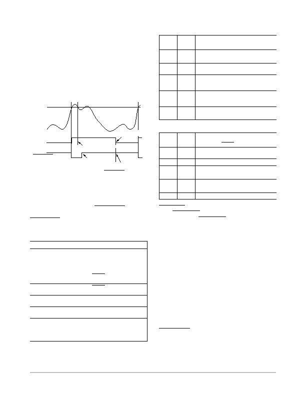
3. Read the status register to identify the interrupt
source.
4. Mask the interrupt source by setting the
appropriate mask bit in the interrupt mask registers
(from Reg. 0x08 to Reg. 0x0A).
5. Take the appropriate action for a given interrupt
source.
6. Exit the interrupt handler.
7. Periodically poll the status register. If the interrupt
status bit clears, reset the corresponding interrupt
mask bit to 0. The SMBusALERT
output and
status bits then behave as shown in Figure 31.
Figure 31. Handling SMBusALERT
TEMPERATURE
INTERRUPT MASK BIT
CLEARED
(SMBusALERT REARMED)
CLEARED ON READ
(TEMP BELOW LIMIT)
INTERRUPT
MASK BIT SET
HIGH LIMIT
SMBusALERT
STICKY
STATUS BIT
TEMP BACK IN LIMIT
(STATUS BIT STAYS SET)
Interrupt Masking Register
Mask Registers 1, 2, and 3 are located at Addresses 0x08,
0x09, and 0x0A. These allow individual interrupt sources to
be masked out to prevent the SMBusALERT
interrupts.
Masking the interrupt source prevents only the
SMBusALERT
from being asserted; the appropriate status bit
is still set as normal.
Table 20. MASK REGISTER 1 (REG. 0X08)
Bit #
Name
Description
7
LH
1 masks the ALERT
for the local high
temperature.
6
LL
1 masks the ALERT
for the local low
temperature.
5
R1H
1 masks the ALERT
for the Remote 1
high temperature.
4
R1L
1 masks the ALERT
for the Remote 1
low temperature.
3
R1D
1 masks the ALERT
for the Remote 1
diode errors.
2
R2H
1 masks the ALERT
for the Remote 2
high temperature.
1
R2L
1 masks the ALERT
for the Remote 2
low temperature.
0
R2D
1 masks the ALERT
for the Remote 2
diode errors.
Table 21. MASK REGISTER 2 (REG. 0X09)
Bit #
Name
Description
7
Res
Reserved
6
Res
Reserved
5
Res
Reserved
4
T%
1 masks the ALERT
for the THERM
%
on-time limit.
3
TA
1 masks the ALERT
for the THERM
limit
being exceeded and the THERM
output
signal being asserted.
2
TS
1 masks the ALERT
for the THERM
state;
has no effect on ALERT
in ALERT
comp
mode.
1
Res
Reserved
0
Res
Reserved
Table 22. MASK REGISTER 3 (REG. 0X0A)
Bit #
Name
Description
7
F1S
1 masks the ALERT
for Fan 1 stalling.
6
FA
1 masks the ALERT
for fans at ALARM
speed.
5
F2S
1 masks the ALERT
for Fan 2 stalling.
4
Res
Reserved
3
Res
Reserved
2
Res
Reserved
1
Res
Reserved
0
Res
Reserved
FAN_FAULT
Output
The FAN_FAULT
output signals when one or both of the
fans stall. Pin 8, the FAN_FAULT
output, is a dual-function
pin. It defaults to being a FAN_FAULT
output but can be
reconfigured as an analog input reference for the THERM
input. To do this, set the FAN_FAULT
/REF (Bit 7) in
Configuration Register 4 (Address 0x04) to 1.
Fault Queue
The ADM1034 has a programmable fault queue option
that lets the user program the number of out-of-limit
measurements allowable before generating an ALERT
. The
fault queue affects only temperature measurement channels
and is only operational in SMBusALERT
mode. It performs
some simple filtering, which is particularly useful at the
higher conversion rates (16, 32, and 64
conversions/second), where averaging is not carried out.
There is a queue for each of the temperature channels. If
L (the number programmed to the fault queue) or more
consecutive out-of-limit readings are made on the same
temperature channel, the fault queue fills, and the
SMBusALERT
output triggers. To fill the fault queue, one
needs L or more consecutive out of limits on the internal
相關PDF資料 |
PDF描述 |
|---|---|
| ADN8810ACPZ-REEL7 | IC CURRENT SOURCE(12BIT) 24LFCSP |
| ADP2140ACPZ3328R7 | IC REG DL BCK/LINEAR 10LFCSP |
| ADP5022ACBZ-6-R7 | IC REG TRPL BCK/LINEAR 16WLCSP |
| ADP5041ACPZ-1-R7 | IC REG TRPL BCK/LINEAR 20-LFCSP |
| ADP5042ACPZ-2-R7 | IC REG TRPL BCK/LINEAR 20LFCSP |
相關代理商/技術參數 |
參數描述 |
|---|---|
| ADM1034ARQZ-REEL7 | 功能描述:IC THERM/FAN SPEED CTRLR 16-QSOP RoHS:是 類別:集成電路 (IC) >> PMIC - 熱管理 系列:- 標準包裝:1 系列:- 功能:溫度監控系統(傳感器) 傳感器類型:內部和外部 感應溫度:-40°C ~ 125°C,外部傳感器 精確度:±2.5°C 本地(最大值),±5°C 遠程(最大值) 拓撲:ADC,比較器,寄存器庫 輸出類型:2 線 SMBus? 輸出警報:無 輸出風扇:無 電源電壓:2.7 V ~ 5.5 V 工作溫度:-40°C ~ 125°C 安裝類型:表面貼裝 封裝/外殼:SOT-23-8 供應商設備封裝:SOT-23-8 包裝:Digi-Reel® 其它名稱:296-22675-6 |
| ADM1040 | 制造商:AD 制造商全稱:Analog Devices 功能描述:Power Supply Monitor ASIC |
| ADM1041 | 制造商:AD 制造商全稱:Analog Devices 功能描述:Secondary-Side Controller with Current Share and Housekeeping |
| ADM1041A | 制造商:AD 制造商全稱:Analog Devices 功能描述:Secondary-Side Controller with Current Share and Housekeeping |
| ADM1041AARQZ | 功能描述:IC SECONDARY SIDE CTRLR 24QSOP RoHS:是 類別:集成電路 (IC) >> PMIC - 電源控制器,監視器 系列:- 產品培訓模塊:Lead (SnPb) Finish for COTS Obsolescence Mitigation Program 標準包裝:2,500 系列:- 應用:多相控制器 輸入電壓:- 電源電壓:9 V ~ 14 V 電流 - 電源:- 工作溫度:-40°C ~ 85°C 安裝類型:表面貼裝 封裝/外殼:40-WFQFN 裸露焊盤 供應商設備封裝:40-TQFN-EP(5x5) 包裝:帶卷 (TR) |
發布緊急采購,3分鐘左右您將得到回復。