- 您現在的位置:買賣IC網 > Datasheet目錄39 > ADM1034ARQZ-REEL (ON Semiconductor)IC THERM/FAN SPEED CTRLR 16-QSOP Datasheet資料下載
參數資料
| 型號: | ADM1034ARQZ-REEL |
| 廠商: | ON Semiconductor |
| 文件頁數: | 26/38頁 |
| 文件大小: | 427K |
| 描述: | IC THERM/FAN SPEED CTRLR 16-QSOP |
| 產品變化通告: | MFG CHG Notification ADI to ON Semi |
| 標準包裝: | 2,500 |
| 功能: | 風扇控制,溫度監控器 |
| 傳感器類型: | 內部和外部 |
| 感應溫度: | -40°C ~ 125°C,外部傳感器 |
| 精確度: | ±1°C |
| 拓撲: | ADC,比較器,多路復用器,寄存器庫 |
| 輸出類型: | SMBus? |
| 輸出警報: | 是 |
| 輸出風扇: | 是 |
| 電源電壓: | 3 V ~ 5.5 V |
| 工作溫度: | -40°C ~ 125°C |
| 安裝類型: | 表面貼裝 |
| 封裝/外殼: | 16-SSOP(0.154",3.90mm 寬) |
| 供應商設備封裝: | 16-QSOP |
| 包裝: | 帶卷 (TR) |
第1頁第2頁第3頁第4頁第5頁第6頁第7頁第8頁第9頁第10頁第11頁第12頁第13頁第14頁第15頁第16頁第17頁第18頁第19頁第20頁第21頁第22頁第23頁第24頁第25頁當前第26頁第27頁第28頁第29頁第30頁第31頁第32頁第33頁第34頁第35頁第36頁第37頁第38頁
ADM1034
http://onsemi.com
26
The ADM1034 can be configured so that Fan 1 or Fan 2
can be controlled by either the local temperature, or by the
Remote 1 or Remote 2 temperatures.
Table 31. DRIVE X BHVR BITS
Bits
DRIVE x BHVR
00
Local Temperature Controls Fan x
01
Remote 1 Temperature Controls Fan x
10
Remote 2 Temperature Controls Fan x
11
Fan x Runs at Full Speed
By default, Remote 1 controls Fan 1, and Remote 2
controls Fan 2. If the ADM1034 is in single-channel mode
and one of the fans is set up to run from a temperature
channel that is not being measured, the drive X BHVR bits
are set to 11 and the fan is run at full speed.
Look-up Table Hysteresis
The user can program a hysteresis to be applied to the
look-up table. The advantage of this is apparent if the
temperature is cycling around one of the threshold
temperatures and causing the fan speed to switch between
the two speeds, particularly when the look-up table is
configured in discrete mode. It would not be as important in
the linear mode.
Programming the Look-up Table Hysteresis
The look-up tables hysteresis register is at Address 0x3A.
A hysteresis value of between 0癈 and 15癈 can be
programmed with a resolution of 1癈 and applied to all the
temperature thresholds. Table 32 gives examples of values
for programming.
Table 32. PROGRAMMING THE HYSTERESIS
Code
Hysteresis Value
0000 0000
0癈
0000 0001
1癈
0000 0010
2癈
0000 0101
5癈 = Default
0000 1000
8癈
0000 1111
15癈
Programming the THERM
Limit for Each Temperature
Channel
THERM
is the absolute maximum temperature allowed
on a temperature channel. Above this temperature, a
component such as the CPU or VRM may be operating
beyond its safe operating limit. When the temperature
measured exceeds THERM
, all fans are driven at full speed
to provide critical system cooling. The fans remain running
at full speed until the temperature drops below THERM
Hysteresis. The hysteresis value is programmable; its
default is 5癈. If the Boost Disable bit (Bit 1) is set in
Configuration Register 2, the fans do not run to full speed.
The THERM
limit is considered the maximum worst-case
operating temperature of the system. Exceeding any
THERM
limit runs all fans at full speed, a condition with
very negative acoustic effects. This limit should be set up as
a fail-safe and not exceeded under normal system operating
conditions.
The THERM
temperature limit registers are listed in
Table 33.
Table 33. THERM
HYSTERESIS REGISTERS
Address
Description
Default
0x0D
Local THERM
Limit
0x95 (85癈)
0x10
Remote 1 THERM
Limit
0x95 (85癈)
0x13
Remote 2 THERM
Limit
0x95 (85癈)
The THERM
hysteresis register is at Address 0x1A. A
hysteresis value is programmed and applied to all three
temperature channels; Local, Remote 1, and Remote 2. A
THERM
hysteresis value of between 0癈 and 15癈 can be
programmed with a resolution of 1癈. Table 33 gives some
examples.
Table 34. PROGRAMMING THERM
HYSTERESIS
Code
Hysteresis Value
0000 0000
0癈
0000 0001
1癈
0000 0010
2癈
0000 0101
5癈 = Default
0000 1000
8癈
0000 1111
15癈
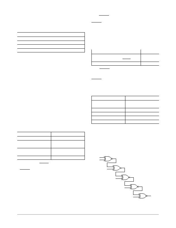
XOR Tree Test Mode
The ADM1034 includes an XOR tree test mode. This is
useful for in circuit test equipment at board level testing. By
applying stimulus to the pins included in the XOR test, it is
possible to detect opens or shorts on the system board.
Figure 43 shows the signals that are exercised in the XOR
tree test mode. The XOR tree test is enabled by setting the
XOR bit (Bit 3) in Configuration 4 Register (0x04).
Figure 43. XOR Tree Test
ALERT
LOCATION
FAN_FAULT
/REF
THERM
TACH1
DRIVE2
DRIVE1
相關PDF資料 |
PDF描述 |
|---|---|
| ADN8810ACPZ-REEL7 | IC CURRENT SOURCE(12BIT) 24LFCSP |
| ADP2140ACPZ3328R7 | IC REG DL BCK/LINEAR 10LFCSP |
| ADP5022ACBZ-6-R7 | IC REG TRPL BCK/LINEAR 16WLCSP |
| ADP5041ACPZ-1-R7 | IC REG TRPL BCK/LINEAR 20-LFCSP |
| ADP5042ACPZ-2-R7 | IC REG TRPL BCK/LINEAR 20LFCSP |
相關代理商/技術參數 |
參數描述 |
|---|---|
| ADM1034ARQZ-REEL7 | 功能描述:IC THERM/FAN SPEED CTRLR 16-QSOP RoHS:是 類別:集成電路 (IC) >> PMIC - 熱管理 系列:- 標準包裝:1 系列:- 功能:溫度監控系統(傳感器) 傳感器類型:內部和外部 感應溫度:-40°C ~ 125°C,外部傳感器 精確度:±2.5°C 本地(最大值),±5°C 遠程(最大值) 拓撲:ADC,比較器,寄存器庫 輸出類型:2 線 SMBus? 輸出警報:無 輸出風扇:無 電源電壓:2.7 V ~ 5.5 V 工作溫度:-40°C ~ 125°C 安裝類型:表面貼裝 封裝/外殼:SOT-23-8 供應商設備封裝:SOT-23-8 包裝:Digi-Reel® 其它名稱:296-22675-6 |
| ADM1040 | 制造商:AD 制造商全稱:Analog Devices 功能描述:Power Supply Monitor ASIC |
| ADM1041 | 制造商:AD 制造商全稱:Analog Devices 功能描述:Secondary-Side Controller with Current Share and Housekeeping |
| ADM1041A | 制造商:AD 制造商全稱:Analog Devices 功能描述:Secondary-Side Controller with Current Share and Housekeeping |
| ADM1041AARQZ | 功能描述:IC SECONDARY SIDE CTRLR 24QSOP RoHS:是 類別:集成電路 (IC) >> PMIC - 電源控制器,監視器 系列:- 產品培訓模塊:Lead (SnPb) Finish for COTS Obsolescence Mitigation Program 標準包裝:2,500 系列:- 應用:多相控制器 輸入電壓:- 電源電壓:9 V ~ 14 V 電流 - 電源:- 工作溫度:-40°C ~ 85°C 安裝類型:表面貼裝 封裝/外殼:40-WFQFN 裸露焊盤 供應商設備封裝:40-TQFN-EP(5x5) 包裝:帶卷 (TR) |
發布緊急采購,3分鐘左右您將得到回復。