- 您現在的位置:買賣IC網 > PDF目錄385408 > HTG2190 (Holtek Semiconductor Inc.) 8-Bit 1024 Pixel LCD Microcontroller PDF資料下載
參數資料
| 型號: | HTG2190 |
| 廠商: | Holtek Semiconductor Inc. |
| 元件分類: | 8位微控制器 |
| 英文描述: | 8-Bit 1024 Pixel LCD Microcontroller |
| 中文描述: | 8位單片機1024像素LCD |
| 文件頁數: | 27/64頁 |
| 文件大小: | 417K |
| 代理商: | HTG2190 |
第1頁第2頁第3頁第4頁第5頁第6頁第7頁第8頁第9頁第10頁第11頁第12頁第13頁第14頁第15頁第16頁第17頁第18頁第19頁第20頁第21頁第22頁第23頁第24頁第25頁第26頁當前第27頁第28頁第29頁第30頁第31頁第32頁第33頁第34頁第35頁第36頁第37頁第38頁第39頁第40頁第41頁第42頁第43頁第44頁第45頁第46頁第47頁第48頁第49頁第50頁第51頁第52頁第53頁第54頁第55頁第56頁第57頁第58頁第59頁第60頁第61頁第62頁第63頁第64頁
HTG2190
Rev. 1.00
27
June 29, 2001
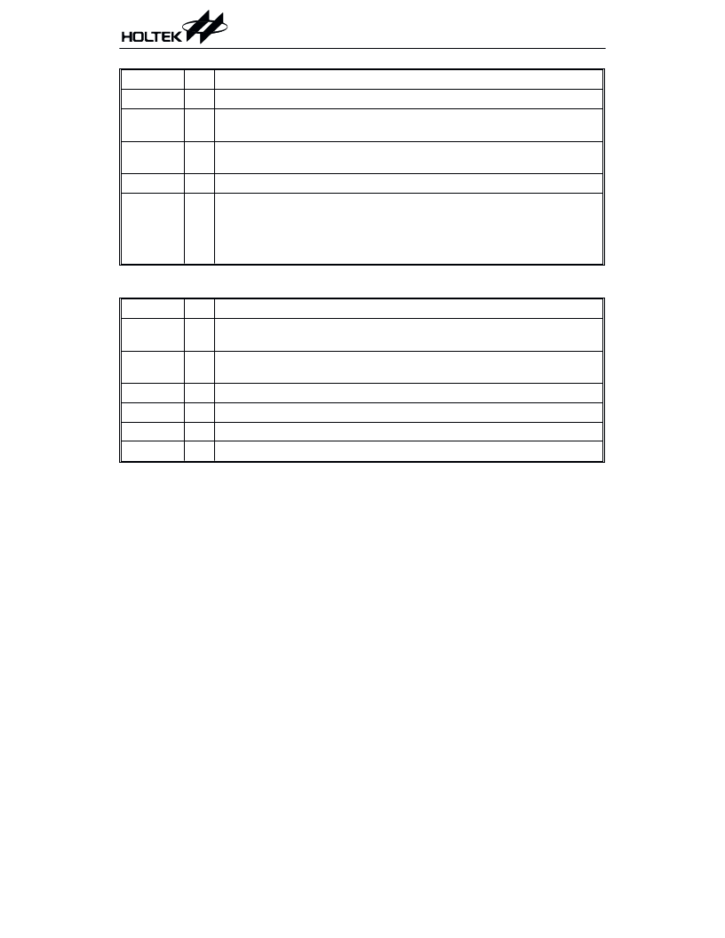
Label
Bits
Function
0~2
Unused bit, read as 0
TE
3
Defines the TMR0/TMR1 active edge of timer/event counter
(0=active on low to high; 1=active on high to low)
TON
4
Enable/disable timer counting
(0=disabled; 1=enabled)
5
Unused bit, read as 0
TM1, TM0
7, 6
Define the operating mode (TM1, TM0)
01=Event count mode (external clock)
10=Timer mode (internal clock)
11=Unused
00=Unused
TMR0C/TMR1C register
Label
Bits
Function
FAST
0
0=speed-up 32K x'tal (default)
1=Non-speed-up 32K x'tal
RTF
1
Select the R-to-F function
0=disable R-to-F (default), 1=enable R-to-F
RTMR0
2
Select the TMR0 pull-high resistor (1=with pull-high; 0=without pull-high)
RTMR1
3
Select the TMR1 pull-high resistor (1=with pull-high; 0=without pull-high)
VDET
4
Supply voltage detection circuit (1=enable VDET, 0=disable VDET)
5~7
Unused bit, read as "0"
X'TALC register
Counter 1 operates in the same manner as
Timer/Event Counter 0.
The TMR0C is the Timer/Event Counter 0 con-
trol register, which defines the Timer/Event
Counter 0 options. The Timer/Event Counter 1
has the same options as the Timer/Event Coun-
ter 0 and is defined by TMR1C.
The timer/event counter control registers de-
fine the operating mode, counting enable or dis-
able and active edge.
The TM0, TM1 bits define the operating mode.
The event count mode is used to count external
events, which implies that the clock source co-
mes from an external (TMR0/TMR1) pin. The
timer mode functions as a normal timer with
the clock source coming from the instruction
clock. The pulse width measurement mode can
be used to count the high or low level duration
of an external signal (TMR0/TMR1). The count-
ing method is based on the instruction clock.
In the event count or timer mode, once the
timer/event counter starts counting, it will
count from the current contents in the
timer/event counter to FFFFH. Once overflow
occurs, the counter is reloaded from the
timer/event counter preload register and gener-
ates a corresponding interrupt request flag
相關PDF資料 |
PDF描述 |
|---|---|
| HTIP117D | PNP EPITAXIAL PLANAR TRANSISTOR |
| HTM1505 | RELATIVE HUMIDITY AND TEMPERATURE MODULE |
| HTM2500 | RELATIVE HUMIDITY/ TEMPERATURE MODULE |
| HTS2010SMD | TEMPERATURE AND RELATIVE HUMIDITY SENSOR |
| HTVDS84 | 8-Bit High Performance Microcontroller With Macro Instruction and Voice Synthesizer and Tone Generator(高性能、8位微控制器,帶宏指令、聲話音成器和聲音發生器) |
相關代理商/技術參數 |
參數描述 |
|---|---|
| HTG2190_02 | 制造商:HOLTEK 制造商全稱:Holtek Semiconductor Inc 功能描述:8-Bit 1024 Pixel Dot Matrix LCD MCU Series |
| HTG3110 | 制造商:未知廠家 制造商全稱:未知廠家 功能描述:Speech Synthesizer |
| HTG3400 | 制造商:HUMIREL 制造商全稱:HUMIREL 功能描述:RELATIVE HUMIDITY AND TEMPERATURE MODULE |
| HTG3413CFB | 制造商:HUMIREL 制造商全稱:HUMIREL 功能描述:RELATIVE HUMIDITY AND TEMPERATURE MODULE |
| HTG3413CH | 制造商:HUMIREL 制造商全稱:HUMIREL 功能描述:RELATIVE HUMIDITY AND TEMPERATURE MODULE |
發布緊急采購,3分鐘左右您將得到回復。