- 您現在的位置:買賣IC網 > PDF目錄361044 > LMX9820A (National Semiconductor Corporation) Bluetooth Serial Port Module PDF資料下載
參數資料
| 型號: | LMX9820A |
| 廠商: | National Semiconductor Corporation |
| 英文描述: | Bluetooth Serial Port Module |
| 中文描述: | 藍牙串行端口模塊 |
| 文件頁數: | 39/44頁 |
| 文件大小: | 579K |
| 代理商: | LMX9820A |
第1頁第2頁第3頁第4頁第5頁第6頁第7頁第8頁第9頁第10頁第11頁第12頁第13頁第14頁第15頁第16頁第17頁第18頁第19頁第20頁第21頁第22頁第23頁第24頁第25頁第26頁第27頁第28頁第29頁第30頁第31頁第32頁第33頁第34頁第35頁第36頁第37頁第38頁當前第39頁第40頁第41頁第42頁第43頁第44頁
Revision 1.0
39
www.national.com
L
15.0 Soldering
(Continued)
15.0 Soldering
The LMX9820A bumps are designed to melt as part of the
Surface Mount Assembly (SMA) process. The LMX9820A
is assembled with a high-temperature solder alloy to
ensure there are no re-reflow conditions imposed upon the
module when reflowed to a PCB with these typical low tem-
perature 60/40 (S = 183°C, L = 188°C), 62/36/2 (E =
179°C), or 63/37 (E = 183°C) solder alloys.
Where:
S: Solidus
– Denotes the points in a phase diagram representing
the temperature at which the solder composition be-
gins to melt during heating, or complete freezing dur-
ing cooling.
L: Liquidus
– Denotes the points in a phase diagram representing
the temperature at which the solder has molten com-
ponents. The temperature that melting starts at.
E: Eutectic
– Denotes solid to liquid without a plastic phase.
The low-temperature solder alloy will reflow with the solder
bump and provide the maximum allowable solder-joint reli-
ability.
Reflow at a peak of 215 --> 220°C (approximately 30 sec-
onds at peak). Do not to exceed 220°C, measured in close
proximity of the modules. to avoid any potential re-reflow
conditions.
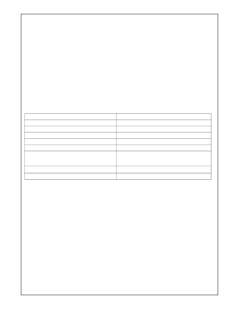
Table 41 and Figure 27 on page 40 provide the soldering
details required to properly solder the LMX9820A to stan-
dard PCBs. The illustration serves only as a guide and
National is not liable if a selected profile does not work.
Table 41. Soldering Details
Parameter
Value
PCB Land Pad Diameter
24 mil
PCB Solder Mask Opening
30 mil
PCB Finish (HASL details)
63/37 (difference in thickness < 28 micron)
Stencil Aperture
28 mil
Stencil Thickness
5 mil
Solder Paste Used
Low temperature 60/40 (S = 183°C, L = 188°C),
62/36/2 (E = 179°C),
or 63/37 (E = 183°C) solder alloys
1
Flux Cleaning Process
No Clean Flux System
1
Reflow Profiles
See Figure 27 on page 40
1.
Typically defined by customer.
相關PDF資料 |
PDF描述 |
|---|---|
| LMX9820ASM | Bluetooth Serial Port Module |
| LMX9820 | Bluetooth Serial Port Module |
| LMX9820SB | Bluetooth Serial Port Module |
| LMX9820SBX | Bluetooth Serial Port Module |
| LP3882ESX-1.2 | 1.5A Fast-Response Ultra Low Dropout Linear |
相關代理商/技術參數 |
參數描述 |
|---|---|
| LMX9820ADEV | 制造商:Texas Instruments 功能描述:KIT DEV FOR LMX9820 |
| LMX9820ADONGLE/NOPB | 制造商:Texas Instruments 功能描述:KIT REF DESIGN FOR LMX9820 |
| LMX9820ASM | 制造商:Texas Instruments 功能描述:BLUETOOTH MODULE, SMD, 9820, FR4129 |
| LMX9820ASM/NOPB | 制造商:Texas Instruments 功能描述:IC MODULE BLUETOOTH 116-LTCC |
| LMX9820ASMX | 制造商:NSC 制造商全稱:National Semiconductor 功能描述:Bluetooth Serial Port Module |
發布緊急采購,3分鐘左右您將得到回復。