- 您現在的位置:買賣IC網 > PDF目錄98282 > TPS51317RGBR (TEXAS INSTRUMENTS INC) SWITCHING REGULATOR, 1500 kHz SWITCHING FREQ-MAX, PQCC20 PDF資料下載
參數資料
| 型號: | TPS51317RGBR |
| 廠商: | TEXAS INSTRUMENTS INC |
| 元件分類: | 穩壓器 |
| 英文描述: | SWITCHING REGULATOR, 1500 kHz SWITCHING FREQ-MAX, PQCC20 |
| 封裝: | 4 X 3.50 MM, GREEN, PLASTIC, QFN-20 |
| 文件頁數: | 12/28頁 |
| 文件大小: | 1000K |
| 代理商: | TPS51317RGBR |
第1頁第2頁第3頁第4頁第5頁第6頁第7頁第8頁第9頁第10頁第11頁當前第12頁第13頁第14頁第15頁第16頁第17頁第18頁第19頁第20頁第21頁第22頁第23頁第24頁第25頁第26頁第27頁第28頁
SLUSAH9
– MARCH 2011
These devices have limited built-in ESD protection. The leads should be shorted together or the device placed in conductive foam
during storage or handling to prevent electrostatic damage to the MOS gates.
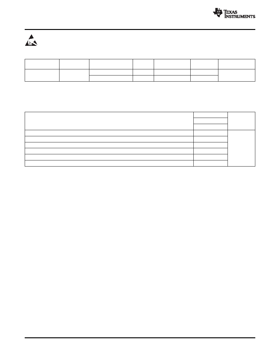
Table 1. ORDERING INFORMATION(1)
MINIMUM
TA
PACKAGE(2)
ORDERING NUMBER
PINS
OUTPUT SUPPLY
ECO PLAN
QUANTITY
TPS51317RGBR
20
Tape and reel
3000
Green (RoHS and
Plastic QFN
-40
°C to 85°C
no Pb/Br)
(RGB)
TPS51317RGBT
20
Mini reel
250
(1)
For the most current package and ordering information, see the Package Option Addendum at the end of this document, or visit the TI
website at www.ti.com.
(2)
Package drawings, standard packing quantities, thermal data, symbolization, and PCB design guidelines are available at
THERMAL INFORMATION
TPS51317
THERMAL METRIC(1)
RGB
UNITS
20 PINS
θJA
Junction-to-ambient thermal resistance(2)
35.5
θJCtop
Junction-to-case (top) thermal resistance(3)
39.6
θJB
Junction-to-board thermal resistance(4)
12.4
°C/W
ψJT
Junction-to-top characterization parameter(5)
0.5
ψJB
Junction-to-board characterization parameter(6)
12.5
θJCbot
Junction-to-case (bottom) thermal resistance(7)
3.7
(1)
For more information about traditional and new thermal metrics, see the IC Package Thermal Metrics application report, SPRA953.
(2)
The junction-to-ambient thermal resistance under natural convection is obtained in a simulation on a JEDEC-standard, high-K board, as
specified in JESD51-7, in an environment described in JESD51-2a.
(3)
The junction-to-case (top) thermal resistance is obtained by simulating a cold plate test on the package top. No specific
JEDEC-standard test exists, but a close description can be found in the ANSI SEMI standard G30-88.
(4)
The junction-to-board thermal resistance is obtained by simulating in an environment with a ring cold plate fixture to control the PCB
temperature, as described in JESD51-8.
(5)
The junction-to-top characterization parameter,
ψJT, estimates the junction temperature of a device in a real system and is extracted
from the simulation data for obtaining
θJA, using a procedure described in JESD51-2a (sections 6 and 7).
(6)
The junction-to-board characterization parameter,
ψJB, estimates the junction temperature of a device in a real system and is extracted
from the simulation data for obtaining
θJA , using a procedure described in JESD51-2a (sections 6 and 7).
(7)
The junction-to-case (bottom) thermal resistance is obtained by simulating a cold plate test on the exposed (power) pad. No specific
JEDEC standard test exists, but a close description can be found in the ANSI SEMI standard G30-88.
2
Copyright
2011, Texas Instruments Incorporated
Product Folder Link(s): TPS51317
相關PDF資料 |
PDF描述 |
|---|---|
| TPS51427ARHBR | DUAL SWITCHING CONTROLLER, PQCC32 |
| TPS51427ARHBT | DUAL SWITCHING CONTROLLER, PQCC32 |
| TPS51461RGET | SWITCHING REGULATOR, 1000 kHz SWITCHING FREQ-MAX, PQCC24 |
| TPS51511RHLT | SWITCHING CONTROLLER, 350 kHz SWITCHING FREQ-MAX, PQCC20 |
| TPS53114PW | SWITCHING CONTROLLER, 700 kHz SWITCHING FREQ-MAX, PDSO16 |
相關代理商/技術參數 |
參數描述 |
|---|---|
| TPS51317RGBT | 功能描述:直流/直流開關轉換器 3.3V/5Vin,6A,DCAP Mode Sync Converter RoHS:否 制造商:STMicroelectronics 最大輸入電壓:4.5 V 開關頻率:1.5 MHz 輸出電壓:4.6 V 輸出電流:250 mA 輸出端數量:2 最大工作溫度:+ 85 C 安裝風格:SMD/SMT |
| TPS51362RVER | 制造商:Texas Instruments 功能描述:22V INPUT, 10A INTEGRATED FET 制造商:Texas Instruments 功能描述:IC REG BUCK SYNC ADJ 10A 28VQFN |
| TPS51362RVET | 制造商:Texas Instruments 功能描述:22V INPUT, 10A INTEGRATED FET 制造商:Texas Instruments 功能描述:IC REG BUCK SYNC ADJ 10A 28VQFN |
| TPS51363 | 制造商:TI 制造商全稱:Texas Instruments 功能描述:22-V Input, 8-A or 10-A Converter With Integrated FET |
| TPS51363RVER | 制造商:Texas Instruments 功能描述:Conv DC-DC Single Step Down 3V to 22V 28-Pin VQFN EP T/R 制造商:Texas Instruments 功能描述:IC REG BCK SYNC ADJ 10/8A 28VQFN |
發布緊急采購,3分鐘左右您將得到回復。