- 您現在的位置:買賣IC網 > PDF目錄373915 > AD7721SQ (ANALOG DEVICES INC) CMOS 16-Bit, 468.75 kHz, Sigma-Delta ADC PDF資料下載
參數資料
| 型號: | AD7721SQ |
| 廠商: | ANALOG DEVICES INC |
| 元件分類: | ADC |
| 英文描述: | CMOS 16-Bit, 468.75 kHz, Sigma-Delta ADC |
| 中文描述: | 1-CH 16-BIT DELTA-SIGMA ADC, SERIAL/PARALLEL ACCESS, CDIP28 |
| 封裝: | CERDIP-28 |
| 文件頁數: | 7/16頁 |
| 文件大小: | 259K |
| 代理商: | AD7721SQ |
AD7721
REV. A
–7–
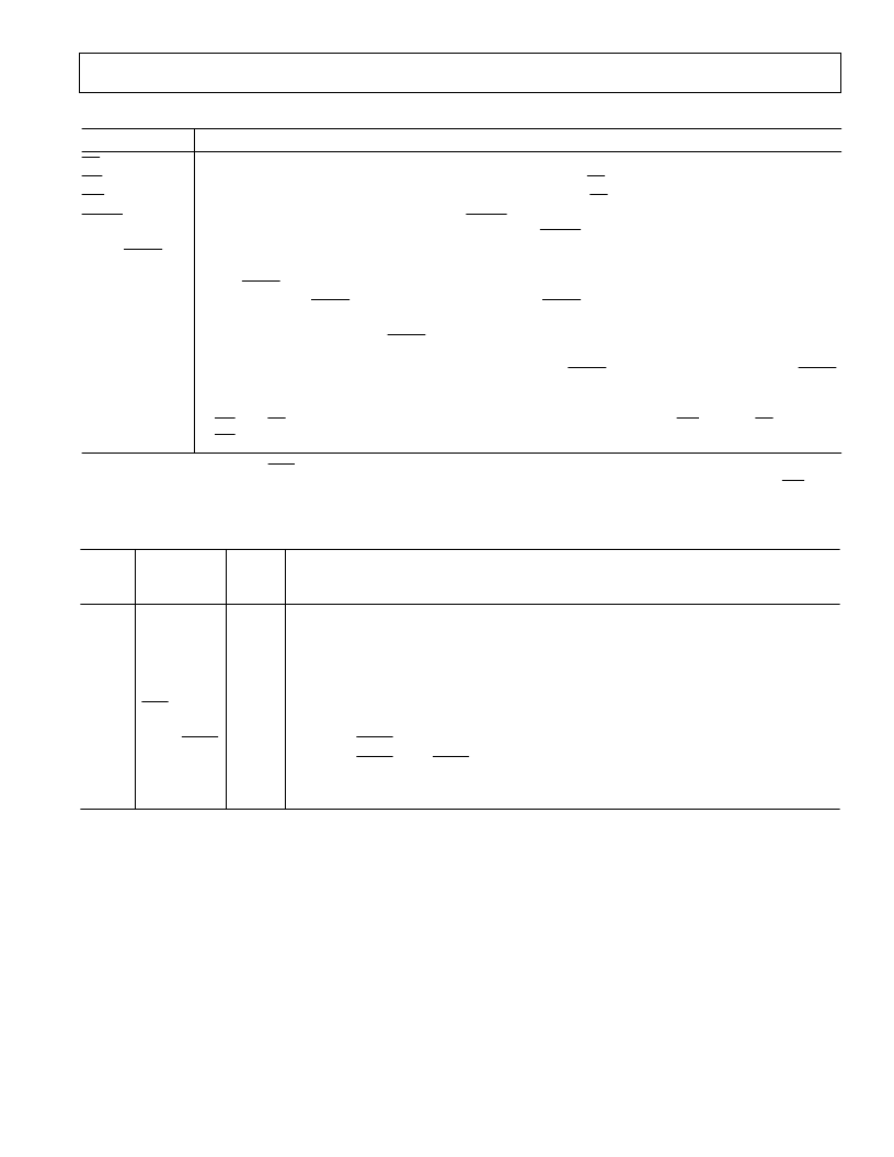
Parallel Mode Only
Mnemonic
Function
CS
RD
WR
DRDY
Chip Select Logic Input.
Read Logic Input. T his digital input is used in conjunction with
CS
to read data from the device.
Write Logic Input. T his digital input is used in conjunction with
CS
to write data to the control register.
In parallel interface mode, a falling edge on
DRDY
indicates that new data is available to be read from the
interface. During a synchronization or calibration cycle,
DRDY
remains high until valid data is available.
T he function of this pin is determined by the state of bit DB3 in the control register. Writing a logic zero to
bit DB3 will program this pin to be a DVAL output. Writing a logic one to bit DB3 will program this pin to
be a
SYNC
input pin.
A rising edge on
SYNC
starts the synchronization cycle.
SYNC
must be pulsed low for at least one clock
cycle.
When switching this pin from
SYNC
mode to DVAL mode, it is important that there are no rising edges on
the pin which could cause resynchronization. For this purpose, an internal pull-up resistor has been included
on this pin. T hus, when the external driver driving this pin in
SYNC
mode is switched off, the DVAL/
SYNC
pin remains high.
T hese pins are both data outputs and control register inputs. Output data is placed on these pins by taking
RD
and
CS
low. Data on these pins is read into the control register by toggling
WR
low with
CS
low. With
RD
high, these pins are high impedance.
DVAL/
SYNC
SDAT A/DB11–
ST BY/DB0
Control functions such as CAL,
UNI
and ST BY, which are available as pins in serial mode, are available as bits in parallel mode.
T able I lists the contents of the control register onboard the AD7721. T his register is written to in parallel mode using the
WR
pin.
T able I. Function of Control Register Bits
Control
Register
Bit
Logical
State
Function
Mode
DB0
ST BY
0
1
0
1
Normal Operation.
Power-Down (Standby) Mode.
Normal Operation.
Writing a Logic “1” to this bit starts a calibration cycle. Internal logic resets this bit to zero at the end of
calibration.
Unipolar Mode.
Bipolar Mode.
Sets DVAL/
SYNC
Pin to DVAL Mode.
Sets DVAL/
SYNC
Pin to
SYNC
Mode.
T his bit is used for testing the AD7721. A logic low MUST be written into this bit for normal
operation.
DB1
CAL
DB2
UNI
0
1
0
1
0
DB3
DVAL/
SYNC
DB9
相關PDF資料 |
PDF描述 |
|---|---|
| AD7722 | 16-Bit, 195 kSPS CMOS, Sigma-Delta ADC |
| AD7722AS | 16-Bit, 195 kSPS CMOS, Sigma-Delta ADC |
| AD7723 | 16-Bit, 1.2 MSPS CMOS, Sigma-Delta ADC |
| AD7723BS | 16-Bit, 1.2 MSPS CMOS, Sigma-Delta ADC |
| AD7724AST | Dual CMOS Modulators |
相關代理商/技術參數 |
參數描述 |
|---|---|
| AD7722 | 制造商:AD 制造商全稱:Analog Devices 功能描述:16-Bit, 195 kSPS CMOS, Sigma-Delta ADC |
| AD7722AS | 制造商:Rochester Electronics LLC 功能描述:16-BIT SIGMA-DELTA CONVERTER I.C. - Bulk 制造商:Analog Devices 功能描述:A/D Converter (A-D) IC |
| AD7722AS-ES | 制造商:Rochester Electronics LLC 功能描述:- Bulk |
| AD7722ASZ | 功能描述:IC ADC 16BIT 195KSPS 44-MQFP RoHS:是 類別:集成電路 (IC) >> 數據采集 - 模數轉換器 系列:- 標準包裝:1 系列:- 位數:14 采樣率(每秒):83k 數據接口:串行,并聯 轉換器數目:1 功率耗散(最大):95mW 電壓電源:雙 ± 工作溫度:0°C ~ 70°C 安裝類型:通孔 封裝/外殼:28-DIP(0.600",15.24mm) 供應商設備封裝:28-PDIP 包裝:管件 輸入數目和類型:1 個單端,雙極 |
| AD7722CSZ | 制造商:Analog Devices 功能描述: |
發布緊急采購,3分鐘左右您將得到回復。