- 您現在的位置:買賣IC網 > PDF目錄373915 > AD7730LBRU (ANALOG DEVICES INC) Bridge Transducer ADC PDF資料下載
參數資料
| 型號: | AD7730LBRU |
| 廠商: | ANALOG DEVICES INC |
| 元件分類: | ADC |
| 英文描述: | Bridge Transducer ADC |
| 中文描述: | 2-CH DELTA-SIGMA ADC, SERIAL ACCESS, PDSO24 |
| 封裝: | TSSOP-24 |
| 文件頁數: | 25/52頁 |
| 文件大小: | 497K |
| 代理商: | AD7730LBRU |
第1頁第2頁第3頁第4頁第5頁第6頁第7頁第8頁第9頁第10頁第11頁第12頁第13頁第14頁第15頁第16頁第17頁第18頁第19頁第20頁第21頁第22頁第23頁第24頁當前第25頁第26頁第27頁第28頁第29頁第30頁第31頁第32頁第33頁第34頁第35頁第36頁第37頁第38頁第39頁第40頁第41頁第42頁第43頁第44頁第45頁第46頁第47頁第48頁第49頁第50頁第51頁第52頁
AD7730/AD7730L
REV. A
–25–
Burnout Currents
T he AD7730 contains two 100 nA constant current generators,
one source current from AV
DD
to AIN(+) and one sink current
from AIN(–) to AGND. T he currents are switched to the se-
lected analog input pair. Both currents are either on or off,
depending on the BO bit of the Mode Register. T hese currents
can be used in checking that a transducer is still operational
before attempting to take measurements on that channel. If the
currents are turned on, allowed flow in the transducer, a mea-
surement of the input voltage on the analog input taken and the
voltage measured is full scale, it indicates that the transducer
has gone open-circuit. If the voltage measured is 0 V, it indicates
that the transducer has gone short circuit. For normal operation,
these burnout currents are turned off by writing a 0 to the BO
bit. T he current sources work over the normal absolute input
voltage range specifications.
RE FE RE NCE INPUT
T he AD7730’s reference inputs, REF IN(+) and REF IN(–),
provide a differential reference input capability. T he common-
mode range for these differential inputs is from AGND to
AV
DD
. T he nominal reference voltage, V
REF
(REF IN(+)—
REF IN(–)), for specified operation is +2.5 V with the HIREF
bit at 0 V and +5 V with the HIREF bit at 1. T he part is also
functional with V
REF
of +2.5 V with the HIREF bit at 1. T his
results in a halving of all input ranges. T he resolution in nV will
be unaltered but will appear halved in terms of counts.
Both reference inputs provide a high impedance, dynamic load.
T he typical average dc input leakage current over temperature
is 8.5
μ
A with HIREF = 1 and V
REF
= +5 V, and 2.5
μ
A with
HIREF = 0 and V
REF
= +2.5 V. Because the input impedance of
each reference input is dynamic, external resistance/capacitance
combinations on these inputs may result in gain errors on the
part.
T he AD7730 can be operated in either ac or dc mode. If the
bridge excitation is fixed dc, the AD7730 should be operated in
dc mode. If the analog input and the reference inputs are externally
chopped before being applied to the part the AD7730 should be
operated in ac mode and not dc mode. In ac mode, it is assumed
that both the analog inputs and reference inputs are chopped
and as a result change phase every alternate chopping cycle. If
the chopping is synchronized by the AD7730 (using the ACX
signals to control the chopping) the part then takes into account
the reversal of the analog input and reference input signals.
T he output noise performance outlined in T ables I through IV
is for an analog input of 0 V and is unaffected by noise on the
reference. T o obtain the same noise performance as shown in
the noise tables over the full input range requires a low noise
reference source for the AD7730. If the reference noise in the
bandwidth of interest is excessive, it will degrade the performance
of the AD7730. In applications where the excitation voltage for
the bridge transducer on the analog input also drives the refer-
ence voltage for the part, the effect of the noise in the excita-
tion voltage will be removed as the application is ratiometric.
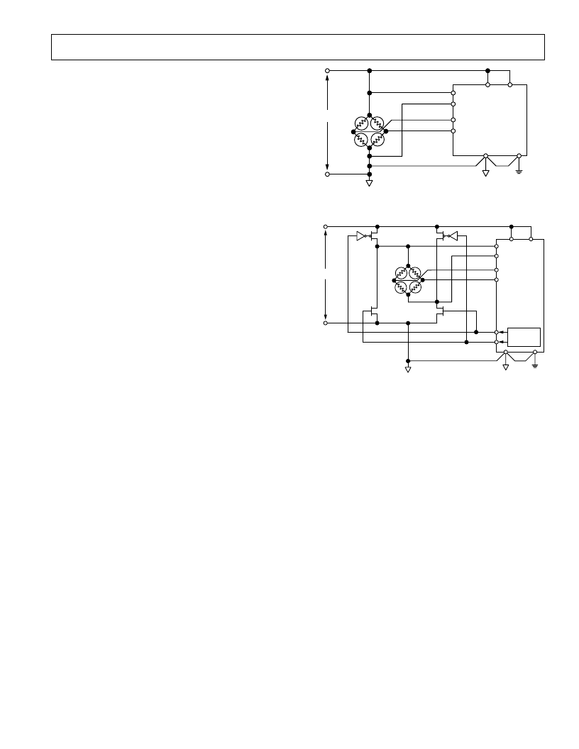
Figure 7 shows how the reference voltage can be connected in a
ratiometric fashion in a dc-excited bridge application. In this
case, the excitation voltage for the AD7730 and the transducer
is a dc voltage. T he HIREF bit of the Mode Register should be
set to 1. Figure 8 meanwhile shows how the reference can be
connected in a ratiometric fashion in an ac-excited bridge
AV
DD
DV
DD
AGND
DGND
AD7730
EXCITATION
VOLTAGE = +5V
IN+
OUT–
IN–
OUT+
REF IN(+)
REF IN(–)
AIN1(+)
AIN1(–)
Figure 7. Ratiometric Generation of Reference in DC-
Excited Bridge Application
AV
DD
DV
DD
VEXCITATION
AGND
DGND
IN+
OUT–
IN–
OUT+
AD7730
REF IN(+)
REF IN(–)
AIN1(+)
AIN1(–)
ACX
ACX
EXCLOCK
Figure 8. Ratiometric Generation of Reference in AC-
Excited Bridge Application
application. In this case, both the reference voltage for the part
and the excitation voltage for the transducer are chopped. Once
again, the HIREF bit should be set to 1.
If the AD7730 is not used in a ratiometric application, a low
noise reference should be used. Recommended 2.5 V reference
voltage sources for the AD7730 include the AD780, REF43
and REF192. If any of these references are used as the reference
source for the AD7730, the HIREF bit should be set to 0. It is
generally recommended to decouple the output of these references
to further reduce the noise level.
Reference Detect
T he AD7730 includes on-chip circuitry to detect if the part
has a valid reference for conversions or calibrations. If the volt-
age between the REF IN(+) and REF IN(–) pins goes below
0.3 V or either the REF IN(+) or REF IN(–) inputs is open
circuit, the AD7730 detects that it no longer has a valid reference.
In this case, the NO REF bit of the Status Register is set to a 1.
If the AD7730 is performing normal conversions and the NO
REF bit becomes active, the part places all ones in the Data
Register. T herefore, it is not necessary to continuously monitor
the status of the NO REF bit when performing conversions. It is
only necessary to verify its status if the conversion result read
from the Data Register is all 1s.
相關PDF資料 |
PDF描述 |
|---|---|
| AD7730 | Bridge Transducer ADC |
| AD7730BN | Bridge Transducer ADC |
| AD7730BR | Bridge Transducer ADC |
| AD7730BRU | Bridge Transducer ADC |
| AD7730L | Bridge Transducer ADC |
相關代理商/技術參數 |
參數描述 |
|---|---|
| AD7730LBRU-REEL | 功能描述:IC ADC TRANSDUCER BRIDGE 24TSSOP RoHS:否 類別:集成電路 (IC) >> 數據采集 - 模擬前端 (AFE) 系列:- 產品培訓模塊:Lead (SnPb) Finish for COTS Obsolescence Mitigation Program 標準包裝:2,500 系列:- 位數:- 通道數:2 功率(瓦特):- 電壓 - 電源,模擬:3 V ~ 3.6 V 電壓 - 電源,數字:3 V ~ 3.6 V 封裝/外殼:32-VFQFN 裸露焊盤 供應商設備封裝:32-QFN(5x5) 包裝:帶卷 (TR) |
| AD7730LBRU-REEL7 | 功能描述:IC ADC TRANSDUCER BRIDGE 24TSSOP RoHS:否 類別:集成電路 (IC) >> 數據采集 - 模擬前端 (AFE) 系列:- 產品培訓模塊:Lead (SnPb) Finish for COTS Obsolescence Mitigation Program 標準包裝:2,500 系列:- 位數:- 通道數:2 功率(瓦特):- 電壓 - 電源,模擬:3 V ~ 3.6 V 電壓 - 電源,數字:3 V ~ 3.6 V 封裝/外殼:32-VFQFN 裸露焊盤 供應商設備封裝:32-QFN(5x5) 包裝:帶卷 (TR) |
| AD7730LBRUZ | 功能描述:IC ADC TRANSDUCER BRIDGE 24TSSOP RoHS:是 類別:集成電路 (IC) >> 數據采集 - 模擬前端 (AFE) 系列:- 產品培訓模塊:Lead (SnPb) Finish for COTS Obsolescence Mitigation Program 標準包裝:2,500 系列:- 位數:- 通道數:2 功率(瓦特):- 電壓 - 電源,模擬:3 V ~ 3.6 V 電壓 - 電源,數字:3 V ~ 3.6 V 封裝/外殼:32-VFQFN 裸露焊盤 供應商設備封裝:32-QFN(5x5) 包裝:帶卷 (TR) |
| AD7730LBRUZ-REEL | 功能描述:IC ADC TRANSDUCER BRIDGE 24TSSOP RoHS:是 類別:集成電路 (IC) >> 數據采集 - 模擬前端 (AFE) 系列:- 產品培訓模塊:Lead (SnPb) Finish for COTS Obsolescence Mitigation Program 標準包裝:2,500 系列:- 位數:- 通道數:2 功率(瓦特):- 電壓 - 電源,模擬:3 V ~ 3.6 V 電壓 - 電源,數字:3 V ~ 3.6 V 封裝/外殼:32-VFQFN 裸露焊盤 供應商設備封裝:32-QFN(5x5) 包裝:帶卷 (TR) |
| AD7730LBRUZ-REEL7 | 功能描述:IC ADC TRANSDUCER BRIDGE 24TSSOP RoHS:是 類別:集成電路 (IC) >> 數據采集 - 模擬前端 (AFE) 系列:- 產品培訓模塊:Lead (SnPb) Finish for COTS Obsolescence Mitigation Program 標準包裝:2,500 系列:- 位數:- 通道數:2 功率(瓦特):- 電壓 - 電源,模擬:3 V ~ 3.6 V 電壓 - 電源,數字:3 V ~ 3.6 V 封裝/外殼:32-VFQFN 裸露焊盤 供應商設備封裝:32-QFN(5x5) 包裝:帶卷 (TR) |
發布緊急采購,3分鐘左右您將得到回復。