- 您現(xiàn)在的位置:買賣IC網(wǎng) > PDF目錄373969 > AD9853 (Analog Devices, Inc.) Programmable Digital QPSK/16-QAM Modulator(可編程數(shù)字的四相移鍵控/16-正交幅度調(diào)制的調(diào)節(jié)器) PDF資料下載
參數(shù)資料
| 型號: | AD9853 |
| 廠商: | Analog Devices, Inc. |
| 英文描述: | Programmable Digital QPSK/16-QAM Modulator(可編程數(shù)字的四相移鍵控/16-正交幅度調(diào)制的調(diào)節(jié)器) |
| 中文描述: | 可編程數(shù)字QPSK/16-QAM調(diào)制器(可編程數(shù)字的四相移鍵控/ 16 -正交幅度調(diào)制的調(diào)節(jié)器) |
| 文件頁數(shù): | 25/31頁 |
| 文件大小: | 339K |
| 代理商: | AD9853 |
第1頁第2頁第3頁第4頁第5頁第6頁第7頁第8頁第9頁第10頁第11頁第12頁第13頁第14頁第15頁第16頁第17頁第18頁第19頁第20頁第21頁第22頁第23頁第24頁當(dāng)前第25頁第26頁第27頁第28頁第29頁第30頁第31頁
AD9853
–25–
REV. A
10
(01)
00
(00)
01
(10)
11
(11)
Q
I
a. QPSK Symbol Mapping
1011
(0111)
1010
(0101)
1000
(0100)
1001
(0110)
Q
I
0001
(0010)
0011
(0011)
0010
(0001)
0000
(0000)
0100
(1000)
0101
(1010)
0111
(1011)
0110
(1001)
1110
(1101)
1100
(1100)
1101
(1110)
1111
(1111)
b. D16-QAM Symbol Mapping
1011
(0111)
1001
(0110)
1000
(0100)
1010
(0101)
Q
I
0001
(0010)
0011
(0011)
0010
(0001)
0000
(0000)
0100
(1000)
0110
(1001)
0111
(1011)
0101
(1010)
1110
(1101)
1100
(1100)
1101
(1110)
1111
(1111)
c. 16-QAM Gray-Coded Symbol Mapping
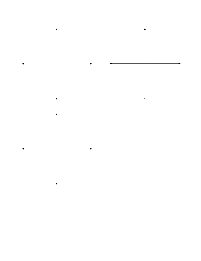
Figure 37. Symbol Mapping for QPSK, 16-QAM, and DQAM,
Spectrum = I
×
COS + Q
×
SIN (Spectrum = I
×
COS – Q
×
SIN)
MIXERS, ADDER, INVERSE SINC FUNCTIONS
At the output of the Interpolation filters, the pulse-shaped, up-
sampled I and Q baseband data is multiplied with digitized
quadrature versions of the carrier, cos(
ω
C
t) and sin(
ω
C
t) respec-
tively, which are provided by a direct digital synthesizer (DDS)
block. The DDS block has a 32-bit tuning word that results in
an extremely fine frequency tuning resolution of f
CLOCK
/2
n
, as
well as extremely fast output frequency switching. The multiplier
outputs are then summed to form the QPSK/QAM-modulated
signal. This signal is then filtered by an inverse sinc filter to
compensate for the SINx/x roll-off function inherent in the
digital-to-analog conversion process. The inverse sinc filter
flattens the gain response across the Nyquist bandwidth. This is
most critical for higher data rate signals that are placed on carri-
ers at the high end of the spectrum where the uncompensated
SINx/x roll-off would be getting progressively steeper. Gain
attenuation across a channel will result in modulation quality
impairments, such as degraded error vector magnitude (EVM).
The spectral inversion bit, when enabled, inverts the Q data at the
input to the adder circuit in the quadrature amplitude modulator
section. This has the effect of reversing the direction of the phase
rotation around the constellation map. Positive phase rotation
on the I/Q constellation plane corresponds to counterclockwise
movement. For example, the symbols in parentheses on the
QPSK constellation in Figure 37 corresponds to a spectral
mapping of I
×
COS – Q
×
SIN. The phase rotation from symbol
value 11 to 01 is a positive 90 degree rotation. Traversing
around the constellation in a positive direction, there are also
positive 90 degree rotations from 01 to 00, 00 to 10, and 10
back to 11. If the spectral invert bit is disabled, providing the
spectral map I
×
COS + Q
×
SIN as shown in Figure 37, a phase
rotation from symbol value 11 to 01 now corresponds to a nega-
tive 90 degrees of phase rotation. Similarly, there are now nega-
tive 90 degree phase rotations from 01 to 00, 00 to 10 and 10
back to 11. In other words, the direction of phase rotation
相關(guān)PDF資料 |
PDF描述 |
|---|---|
| AD9854 | CMOS 300MHz Quadrature Complete-DDS |
| AD9858TLPCB | 1 GSPS Direct Digital Synthesizer |
| AD9858BSV | 1 GSPS Direct Digital Synthesizer |
| AD9858PCB | 1 GSPS Direct Digital Synthesizer |
| AD9858 | 1 GSPS Direct Digital Synthesizer |
相關(guān)代理商/技術(shù)參數(shù) |
參數(shù)描述 |
|---|---|
| AD9853-45PCB | 制造商:AD 制造商全稱:Analog Devices 功能描述:Programmable Digital OPSK/16-QAM Modulator |
| AD9853-65PCB | 制造商:AD 制造商全稱:Analog Devices 功能描述:Programmable Digital OPSK/16-QAM Modulator |
| AD9853AS | 制造商:Analog Devices 功能描述: 制造商:Rochester Electronics LLC 功能描述:- Bulk |
| AD9854 | 制造商:AD 制造商全稱:Analog Devices 功能描述:CMOS 300 MHz Quadrature Complete-DDS |
| AD9854/PCB | 制造商:Analog Devices 功能描述:Evaluation Board For IC Digital Synthesizer Single 制造商:Analog Devices 功能描述:Direct Digital Synthesizer IC (DDS) |
發(fā)布緊急采購,3分鐘左右您將得到回復(fù)。