- 您現(xiàn)在的位置:買賣IC網(wǎng) > PDF目錄373969 > AD9870 (ANALOG DEVICES INC) IF Digitizing Subsystem PDF資料下載
參數(shù)資料
| 型號: | AD9870 |
| 廠商: | ANALOG DEVICES INC |
| 元件分類: | 通信及網(wǎng)絡(luò) |
| 英文描述: | IF Digitizing Subsystem |
| 中文描述: | SPECIALTY TELECOM CIRCUIT, PQFP48 |
| 封裝: | 1.40 MM HEIGHT, PLASTIC, TQFP-48 |
| 文件頁數(shù): | 13/20頁 |
| 文件大小: | 233K |
| 代理商: | AD9870 |
REV. 0
AD9870
–13–
FREQUENCY
–
MHz
1
10
d
–
1
–
2
–
3
–
4
–
5
–
6
3
–
3 BIAS
SETTING
100
1000
0
2
–
2 BIAS
SETTING
1
–
1 BIAS
SETTING
0
–
1 BIAS
SETTING
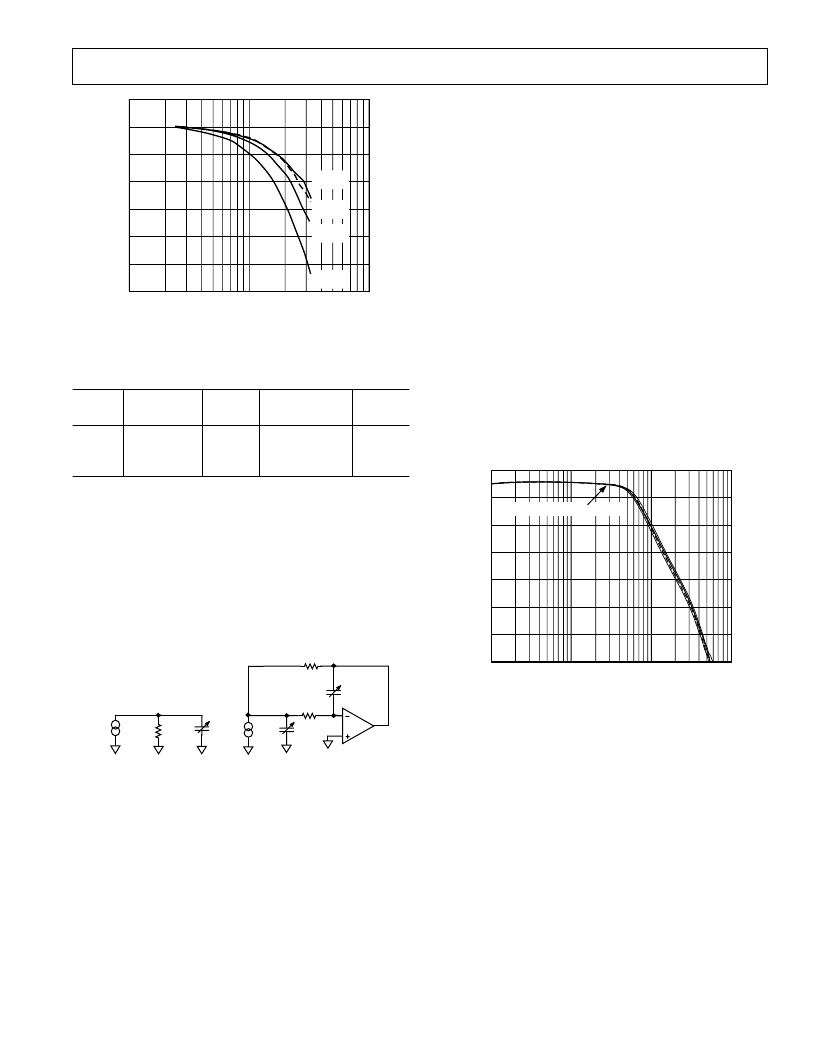
Figure 7e. LNA/Mixer Frequency Response vs. Bias
Setting
Table VII. SPI Registers Associated with LNA/Mixer
A
ddress
(Hex)
Bit
Breakdown
Width
Default Value
Name
0
x01
0x01
0x03
(7:6)
(5:4)
(7)
2
2
1
0
0
0
LNAB
MIXB
ATTEN
ANTIALIAS FILTER
The AD9870 includes a programmable continuous-time third
order antialias filter (AAF) as shown in Figure 8. Its purpose is
to suppress any noise or spectral components occurring at N
×
f
CLK
±
(f
CLK
/8) from aliasing back into the sigma-delta ADC’s
passband centered at
f
CLK
/8. It consists of a programmable
capacitor at the mixer output providing a real pole plus a second
order programmable filter built into the VGA providing a com-
plex pole pair.
C2
C0
R0
180
G
m0
G
m1
C1
R1
R2
C0 AND C1 CONSIST OF 36 NWELL CAPACITORSIN PARALLEL
C3 CONSIST OF 36 POLY-POLY CAPACITORSIN PARALLEL
MIXER
(5MHz LOWPASS)
I-V 2ND ORDER LPF
Figure 8. Equivalent Circuit of Antialias Filter
The AAF is typically tuned during the start-up phase of the
AD9870. The user initiates tuning of the AAF by writing a value to
the AAR (antialias response) register. The following two consid-
erations should be noted when tuning the AAF response. First,
the accuracy of the tuning algorithm is sensitive to on-chip
digital noise. Thus,
placing the ADC in standby (i.e., register STBY)
prior to tuning the AAF is recommended
. Second, although the
default setting of the AAR register is 0x00,
writing 0x00 is not recom-
mended
since all subsequent writes to this register will be ignored
until power to the AD9870 is reapplied to reset this register.
The AAF tuning algorithm works in the following manner. The
AD9870 measures the oscillation frequency of an on-chip RC
oscillator relative to the frequency applied to the CLKP, CLKN
pins. It then uses this measurement in conjunction with the AAR
setting to program the capacitors of the AAF which sets the filters
poles. The on-chip circuitry sets the capacitor-programming
registers (CAPN and CAPP) to the required values based on the
clock frequency and the AAR setting.
The recommended –3 dB cutoff frequency is
f
CLK
/3.2 (selected
by setting AAR = 0x60) since it provides minimal signal attenu-
ation in the passband region of
f
CLK
/8 and sufficient attenuation
of the potential alias components in the transition band region.
For this setting the frequency-scaling resolution is sufficient to
yield less than 10% tuning error with clock frequencies between
13 MHz and 18 MHz. Figure 9a shows the measured response
of the antialias filter when it has been tuned with AAR = 0x60 at
an ADC clock frequency of 18 MHz. The multiple curves show
the possible tuning error due to the finite resolution of the tun-
ing capacitors. In this example, the capacitor across the mixer
load resistors yields a pole at 5 MHz, which degrades the mixer
gain at 2.25 MHz by approximately 0.8 dB. The nominal –3 dB
cutoff frequency of the antialias filter is 5.6 MHz. The nominal
attenuation at the first alias (15.75 MHz) is 28 dB and falls at
60 dB/decade so that the nominal attenuation at 50 MHz is 60 dB.
5
FREQUENCY
–
MHz
0.1
A
–
–
5
–
15
–
25
–
35
–
45
–
55
–
65
1
10
100
2.25MHz IF @ CLK = 18MSPS
Figure 9a. Antialias filter response with AAR = 0x60 and
f
CLK
= 18 MHz. Note, the curves have been normalized
individually to 0 dB at f
0
= 2.25 MHz.
Since the frequency measurements are performed relative to the
clock frequency, the AAF’s normalized frequency response
remains relatively independent of the ADC clock frequency.
There is guaranteed to be sufficient range in the programmable
capacitor arrays to support the response of Figure 9a for clock
frequencies between 13 MHz and 18 MHz with the resolution
indicated. Also, the normalized frequency response of the AAF
remains relatively independent of the programmed –3 dB cutoff
frequency over a 13 MHz to 18 MHz frequency range as shown
in Figure 9b. If the user specifies an unattainable response, the
on-chip circuitry sets CAPN and/or CAPP to the limit of their
ranges and also sets the ERRN and/or ERRP bit to indicate that
the specified response cannot be supported.
相關(guān)PDF資料 |
PDF描述 |
|---|---|
| AD9870EB | IF Digitizing Subsystem |
| AD9873 | Analog Front End Converter for Set-Top Box, Cable Modem |
| AD9873-EB | Analog Front End Converter for Set-Top Box, Cable Modem |
| AD9873JS | Analog Front End Converter for Set-Top Box, Cable Modem |
| AD9874 | IF Digitizing Subsystem |
相關(guān)代理商/技術(shù)參數(shù) |
參數(shù)描述 |
|---|---|
| AD9870AST | 制造商:Rochester Electronics LLC 功能描述:GENERAL PURPOSE IF SUBSYSTEM - Tape and Reel 制造商:Analog Devices 功能描述: |
| AD9870EB | 制造商:AD 制造商全稱:Analog Devices 功能描述:IF Digitizing Subsystem |
| AD9873 | 制造商:AD 制造商全稱:Analog Devices 功能描述:Analog Front End Converter for Set-Top Box, Cable Modem |
| AD9873-EB | 制造商:Analog Devices 功能描述: |
| AD9873JS | 制造商:Analog Devices 功能描述: |
發(fā)布緊急采購,3分鐘左右您將得到回復(fù)。