- 您現在的位置:買賣IC網 > PDF目錄373969 > AD9858 (Analog Devices, Inc.) 1 GSPS Direct Digital Synthesizer PDF資料下載
參數資料
| 型號: | AD9858 |
| 廠商: | Analog Devices, Inc. |
| 元件分類: | XO, clock |
| 英文描述: | 1 GSPS Direct Digital Synthesizer |
| 中文描述: | 1 GSPS的直接數字頻率合成器 |
| 文件頁數: | 19/32頁 |
| 文件大小: | 1412K |
| 代理商: | AD9858 |
第1頁第2頁第3頁第4頁第5頁第6頁第7頁第8頁第9頁第10頁第11頁第12頁第13頁第14頁第15頁第16頁第17頁第18頁當前第19頁第20頁第21頁第22頁第23頁第24頁第25頁第26頁第27頁第28頁第29頁第30頁第31頁第32頁
AD9858
Rev. A | Page 19 of 32
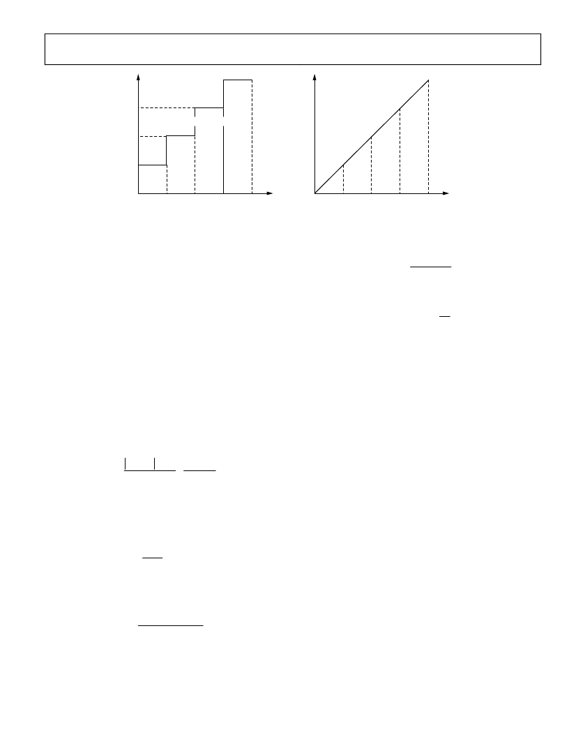
40ns
80ns
TIME
F
120ns
160ns
DELTA FREQUENCY RAMP RATE WORD (
≥
8ns)
8ns
16ns
TIME
F
24ns
32ns
DELTA FREQUENCY TUNING WORD
0
Figure 32. Frequency vs. Time Plots for a Given Sweep Profile
The delta frequency ramp rate word (DFRRW) functions as a
countdown timer, in which the value of the DFRRW is decre-
mented at the rate of SYSCLK/8. This means that the most rapid
frequency word update occurs when a value of 1 is loaded into
the DFRRW, and results in a frequency increment at 1/8 of the
SYSCLK rate. With a SYSCLK of 1 GHz, the frequency can be
incremented at a maximum rate of 125 MHz (DFRRW = 1).
The delta frequency tuning word (DFTW) must specify
whether the frequency sweep should proceed up or down from
the starting frequency (FTW). Therefore, the DFTW is
expressed as a twos complement binary value, in which positive
indicates up and negative indicates down.
A DFRRW value of 0 written to the register stops all frequency
sweeping. There is no automatic stop-at-a-given-frequency
function. The user must calculate the time interval required to
reach the final frequency and then issue a command to write 0
into the DFRRW register. The time required for a frequency
sweep is calculated by the following formula
DFTW
DFRRW
SYSCLK
f
f
T
2
S
F
×
×
=
34
2
where:
T
is the duration of the sweep in seconds.
f
S
is the starting frequency determined by
SYSCLK
FTW
32
2
f
S
×
=
.
f
F
is the final frequency.
The delta frequency step size is given by
31
2
SYSCLK
DFTW
f
×
=
,
remembering that DFTW is a signed (twos complement) value.
The time between each frequency step (
t
) is given by
SYSCLK
DFRRW
t
×
=
8
The value of the stop frequency
f
F
is determined by
t
f
T
f
f
S
F
×
+
=
Returning to Starting Frequency
The original frequency tuning word (FTW), which was written
into the frequency tuning register, does not change at any time
during a sweeping operation. This means that the DDS may be
returned to the sweep starting frequency at any time during a
sweep. Setting the control bit named autoclear frequency
accumulator forces the frequency accumulator to zero, instantly
returning the DDS to the frequency stored as FTW.
Full-Sleep Mode
Setting all of the power-down bits in the control function
register activates full-sleep mode. During the power-down
condition, the clocks associated with the various functional
blocks of the device are turned off, thereby offering a significant
power savings.
SYNCHRONIZATION
SYNCLK and FUD Pins
Timing for the AD9858 is provided via the user-supplied
REFCLK input. The REFCLK input is buffered and is the source
for the internally generated SYSCLK. The frequency of SYSCLK
can be either the same as REFCLK or half that of REFCLK (via
a programmable divide-by-2 function set in the control
function register CFR). The REFCLK input is capable of
handling input frequencies as high as 2 GHz. However, the
device is designed for a maximum SYSCLK frequency of 1 GHz.
Thus, it is mandatory that the divide-by-2 SYSCLK function be
enabled when the frequency of REFCLK is greater than 1 GHz.
相關PDF資料 |
PDF描述 |
|---|---|
| AD9858FDPCB | 1 GSPS Direct Digital Synthesizer |
| AD9859 | 400 MSPS, 10-Bit, 1.8 V CMOS Direct Digital Synthesizer |
| AD9859YSV | 400 MSPS, 10-Bit, 1.8 V CMOS Direct Digital Synthesizer |
| AD9859YSV-REEL7 | 400 MSPS, 10-Bit, 1.8 V CMOS Direct Digital Synthesizer |
| AD9862PCB | Mixed-Signal Front-End (MxFE⑩) Processor for Broadband Communications |
相關代理商/技術參數 |
參數描述 |
|---|---|
| AD9858/FDPCB | 制造商:Analog Devices 功能描述:EVAL KIT FOR FRACTIONAL DIVIDER EVAL BD - Bulk |
| AD9858/PCBZ | 功能描述:BOARD EVAL FOR AD9858 RoHS:是 類別:編程器,開發系統 >> 評估演示板和套件 系列:- 標準包裝:1 系列:PSoC® 主要目的:電源管理,熱管理 嵌入式:- 已用 IC / 零件:- 主要屬性:- 次要屬性:- 已供物品:板,CD,電源 |
| AD9858/TLPCB | 制造商:Analog Devices 功能描述:NCO/DDS, 1GSPS DIRECT DGTL SYNTHESIZER - Bulk |
| AD9858/TLPCBZ | 制造商:Analog Devices 功能描述:EVAL BOARD - Bulk |
| AD9858BSV | 制造商:Rochester Electronics LLC 功能描述:1000 MHZ DDS/DAC - Bulk 制造商:Analog Devices 功能描述:1GHZ DDS/DAC SMD 9858 TQFP100 制造商:Analog Devices 功能描述:Frequency Synthesizer,AD9858 1GHz TQFP |
發布緊急采購,3分鐘左右您將得到回復。