- 您現在的位置:買賣IC網 > PDF目錄374032 > ADSP-21160M (Analog Devices, Inc.) DSP Microcomputer PDF資料下載
參數資料
| 型號: | ADSP-21160M |
| 廠商: | Analog Devices, Inc. |
| 元件分類: | 數字信號處理 |
| 英文描述: | DSP Microcomputer |
| 中文描述: | DSP微機 |
| 文件頁數: | 9/53頁 |
| 文件大小: | 696K |
| 代理商: | ADSP-21160M |
第1頁第2頁第3頁第4頁第5頁第6頁第7頁第8頁當前第9頁第10頁第11頁第12頁第13頁第14頁第15頁第16頁第17頁第18頁第19頁第20頁第21頁第22頁第23頁第24頁第25頁第26頁第27頁第28頁第29頁第30頁第31頁第32頁第33頁第34頁第35頁第36頁第37頁第38頁第39頁第40頁第41頁第42頁第43頁第44頁第45頁第46頁第47頁第48頁第49頁第50頁第51頁第52頁第53頁
–
9
–
REV. 0
ADSP-21160M
Unused inputs should be tied or pulled to VDD or GND,
except for ADDR31
–
0, DATA63
–
0, FLAG3
–
0, and inputs
that have internal pull-up or pull-down resistors (PA, ACK,
BRST, PAGE, CLKOUT, MS3
–
0, RDx, WRx, DMARx,
DMAGx, DTx, DRx, TCLKx, RCLKx, LxDAT7
–
0,
LxCLK, LxACK, TMS, TRST and TDI)
—
these pins can
be left floating. These pins have a logic-level hold circuit
(only enabled on the ADSP-21160M with ID2
–
0 = 00x)
that prevents input from floating internally.
The following symbols appear in the Type column of
Table 2
: A = Asynchronous, G = Ground, I = Input,
O = Output, P = Power Supply, S = Synchronous,
(A/D) = Active Drive, (O/D) = Open Drain, and
T = Three-State (when SBTS is asserted, or when the
ADSP-21160M is a bus slave).
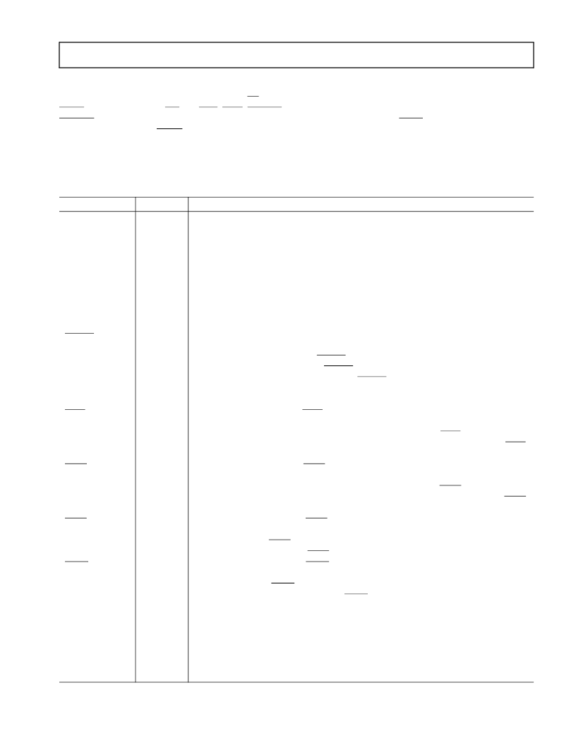
Table 2. Pin Function Descriptions
Pin
ADDR31
–
0
Type
I/O/T
Function
External Bus Address. The ADSP-21160M outputs addresses for external memory and
peripherals on these pins. In a multiprocessor system, the bus master outputs addresses
for read/writes of the internal memory or IOP registers of other ADSP-21160Ms. The
ADSP-21160M inputs addresses when a host processor or multiprocessing bus master
is reading or writing its internal memory or IOP registers. A keeper latch on the DSP
’
s
ADDR31
–
0 pins maintains the input at the level it was last driven (only enabled on the
ADSP-21160M with ID2
–
0 = 00x).
External Bus Data. The ADSP-21160M inputs and outputs data and instructions on
these pins. Pull-up resistors on unused DATA pins are not necessary. A keeper latch on
the DSP
’
s DATA63-0 pins maintains the input at the level it was last driven (only
enabled on the ADSP-21160M with ID2
–
0 = 00x).
Memory Select Lines. These outputs are asserted (low) as chip selects for the corre-
sponding banks of external memory. Memory bank size must be defined in the
SYSCON control register. The MS3
–
0 outputs are decoded memory address lines. In
asyn- chronous access mode, the MS3
–
0 outputs transition with the other address
outputs. In synchronous access modes, the MS3
–
0 outputs assert with the other address
lines; however, they de-assert after the first CLKIN cycle in which ACK is
sampled asserted.
Memory Read Low Strobe. RDL is asserted whenever ADSP-21160M reads from the
low word of external memory or from the internal memory of other ADSP-21160Ms.
External devices, including other ADSP-21160Ms, must assert RDL for reading from
the low word of ADSP-21160M internal memory. In a multiprocessing system, RDL
is driven by the bus master.
Memory Read High Strobe. RDH is asserted whenever ADSP-21160M reads from the
high word of external memory or from the internal memory of other ADSP-21160Ms.
External devices, including other ADSP-21160Ms, must assert RDH for reading from
the high word of ADSP-21160M internal memory. In a multiprocessing system, RDH
is driven by the bus master.
Memory Write Low Strobe. WRL is asserted when ADSP-21160M writes to the low
word of external memory or internal memory of other ADSP-21160Ms. External
devices must assert WRL for writing to ADSP-21160M
’
s low word of internal memory.
In a multiprocessing system, WRL is driven by the bus master.
Memory Write High Strobe. WRH is asserted when ADSP-21160M writes to the high
word of external memory or internal memory of other ADSP-21160Ms. External
devices must assert WRH for writing to ADSP-21160M
’
s high word of internal
memory. In a multiprocessing system, WRH is driven by the bus master.
DRAM Page Boundary. The ADSP-21160M asserts this pin to signal that an external
DRAM page boundary has been crossed. DRAM page size must be defined in the
ADSP-21160M
’
s memory control register (WAIT). DRAM can only be implemented
in external memory Bank 0; the PAGE signal can only be activated for Bank 0 accesses.
In a multiprocessing system PAGE is output by the bus master. A keeper latch on the
DSP
’
s PAGE pin maintains the output at the level it was last driven (only enabled on
the ADSP-21160M with ID2
–
0 = 00x).
DATA63
–
0
I/O/T
MS3
–
0
O/T
RDL
I/O/T
RDH
I/O/T
WRL
I/O/T
WRH
I/O/T
PAGE
O/T
相關PDF資料 |
PDF描述 |
|---|---|
| ADSP-21160MKB-80 | DSP Microcomputer |
| ADSP-21160NKB-95 | DSP Microcomputer |
| ADSP-21160N | Cap-Free, NMOS, 150mA Low Dropout Regulator with Reverse Current Protection |
| ADSP-21160NCB-TBD | Cap-Free, NMOS, 150mA Low Dropout Regulator with Reverse Current Protection |
| ADSP-21161N | DSP Microcomputer |
相關代理商/技術參數 |
參數描述 |
|---|---|
| ADSP-21160MKB-80 | 功能描述:IC DSP CONTROLLER 32BIT 400 BGA RoHS:否 類別:集成電路 (IC) >> 嵌入式 - DSP(數字式信號處理器) 系列:SHARC® 標準包裝:2 系列:StarCore 類型:SC140 內核 接口:DSI,以太網,RS-232 時鐘速率:400MHz 非易失內存:外部 芯片上RAM:1.436MB 電壓 - 輸入/輸出:3.30V 電壓 - 核心:1.20V 工作溫度:-40°C ~ 105°C 安裝類型:表面貼裝 封裝/外殼:431-BFBGA,FCBGA 供應商設備封裝:431-FCPBGA(20x20) 包裝:托盤 |
| ADSP-21160MKBZ-80 | 功能描述:IC DSP CONTROLLER 32BIT 400 BGA RoHS:是 類別:集成電路 (IC) >> 嵌入式 - DSP(數字式信號處理器) 系列:SHARC® 標準包裝:2 系列:StarCore 類型:SC140 內核 接口:DSI,以太網,RS-232 時鐘速率:400MHz 非易失內存:外部 芯片上RAM:1.436MB 電壓 - 輸入/輸出:3.30V 電壓 - 核心:1.20V 工作溫度:-40°C ~ 105°C 安裝類型:表面貼裝 封裝/外殼:431-BFBGA,FCBGA 供應商設備封裝:431-FCPBGA(20x20) 包裝:托盤 |
| ADSP-21160N | 制造商:AD 制造商全稱:Analog Devices 功能描述:DSP Microcomputer |
| ADSP-21160NCB-100 | 功能描述:IC DSP CONTROLLER 32BIT 400BGA RoHS:否 類別:集成電路 (IC) >> 嵌入式 - DSP(數字式信號處理器) 系列:SHARC® 標準包裝:2 系列:StarCore 類型:SC140 內核 接口:DSI,以太網,RS-232 時鐘速率:400MHz 非易失內存:外部 芯片上RAM:1.436MB 電壓 - 輸入/輸出:3.30V 電壓 - 核心:1.20V 工作溫度:-40°C ~ 105°C 安裝類型:表面貼裝 封裝/外殼:431-BFBGA,FCBGA 供應商設備封裝:431-FCPBGA(20x20) 包裝:托盤 |
| ADSP-21160NCB-TBD | 制造商:AD 制造商全稱:Analog Devices 功能描述:DSP Microcomputer |
發布緊急采購,3分鐘左右您將得到回復。