- 您現(xiàn)在的位置:買賣IC網(wǎng) > Datasheet目錄46 > SC418ULTRT (Semtech)IC REG DL BUCK/LINEAR 20MLPQ Datasheet資料下載
參數(shù)資料
| 型號: | SC418ULTRT |
| 廠商: | Semtech |
| 文件頁數(shù): | 20/30頁 |
| 文件大小: | 691K |
| 描述: | IC REG DL BUCK/LINEAR 20MLPQ |
| 產品培訓模塊: | Power Supplies 101 |
| 標準包裝: | 1 |
| 系列: | EcoSpeed® |
| 拓撲: | 降壓(降壓)(1),線性(LDO)(1) |
| 功能: | 任何功能 |
| 輸出數(shù): | 2 |
| 頻率 - 開關: | 1MHz |
| 電壓/電流 - 輸出 1: | 控制器 |
| 電壓/電流 - 輸出 2: | 0.75 V ~ 5.25 V,200mA |
| 帶 LED 驅動器: | 無 |
| 帶監(jiān)控器: | 無 |
| 帶序列發(fā)生器: | 無 |
| 電源電壓: | 3 V ~ 28 V |
| 工作溫度: | -40°C ~ 85°C |
| 安裝類型: | 表面貼裝 |
| 封裝/外殼: | 20-MLPQ |
| 供應商設備封裝: | 20-MLPQ(3x3) |
| 包裝: | 標準包裝 |
| 其它名稱: | SC418ULTRTDKR |
第1頁第2頁第3頁第4頁第5頁第6頁第7頁第8頁第9頁第10頁第11頁第12頁第13頁第14頁第15頁第16頁第17頁第18頁第19頁當前第20頁第21頁第22頁第23頁第24頁第25頁第26頁第27頁第28頁第29頁第30頁
SC418
20
Applications Information (continued)
ENL Logic Control of PWM Operation
When the ENL input exceeds the VIN UVLO threshold of
2.6V, internal logic checks the PGOOD signal. If PGOOD is
high, the switcher is already running and the LDO will start
without affecting the switcher. If PGOOD is low, the device
disables PWM switching until the LDO output has reached
90% of its final value. This delay prevents the additional
current needed by the DH and DL gate drives from over-
loading the LDO at start-up.
In some cases it is desirable to use the V
IN
UVLO feature for
the switcher without using the LDO. This can be done by
connecting the FBL pin directly to VDDA. This disables the
LDO, allowing the ENL pin to be used only for VIN UVLO for
the switcher.
LDO Start-up
Before LDO start-up, the device checks the status of the
following signals to ensure proper operation can be
maintained.
ENL pin
VLDO output
V
IN
input voltage
When the ENL pin is high and V
IN
is available, the LDO will
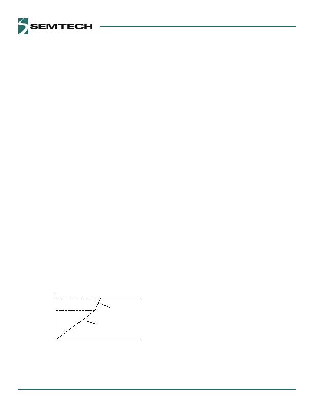
begin start-up. During the initial phase, when VLDO is
near zero, the LDO initiates a current-limited start-up
(typically 5mA) to charge the output capacitor. When
V
LDO
has reached 90% of the final value (as sensed at the
FBL pin), the LDO current limit is increased to 200mA and
the LDO output is quickly driven to the nominal value.
The LDO start-up is shown in Figure 2.
V
VLDO
Final
90% of V
VLDO
Final
Constant current startup
Voltage regulating with
~200mA current limit
Figure 12 LDO Start-Up
.
2.
3.
LDO Switch-Over Operation
The SC48 includes a switch-over function for the LDO.
The switch-over function is designed to increase efficiency
by using the more efficient DC-DC converter to power the
LDO output, avoiding the less efficient LDO regulator
when possible. The switch-over function connects the
VLDO pin directly to the VOUT pin through an internal
switch. When the switch-over is complete the LDO is
turned off, which reduces operating power loss. If the LDO
output is used to bias the SC48, then after switch-over
the device is self-powered from the switching regulator
with the LDO turned off.
After the switcher completes soft-start, the switch-over
logic waits for 32 switching cycles before it starts the
switch-over. There are two methods of completing the
switch-over of V
LDO
to V
OUT
.
In the first method, the LDO is already in regulation when
the DC-DC converter is enabled. As soon as the PGOOD
output goes high, the 32 cycle count is started. The volt-
ages at the VLDO and VOUT pins are then compared; if the
two voltages are within ?00mV of each other, the VLDO
pin connects to the VOUT pin using an internal switch,
and the LDO is turned off.
In the second method, the DC-DC converter is already
running and the LDO is enabled. In this case the 32 cycle
count is started as soon as the LDO reaches 90% of its final
value. At this time, the VLDO and VOUT pins are compared,
and if within ?00mV the switch-over occurs and the LDO
is turned off.
Switch-over Limitations on VOUT and VLDO
Because the internal switch-over circuit always compares
the VOUT and VLDO pins at start-up, there are limitations
on permissible combinations of VOUT and VLDO. Consider
the case where VOUT is programmed to .5V and VLDO is
programmed to .8V. After start-up, the device would
connect VOUT to VLDO and disable the LDO, since the two
voltage are within the ?00mV switch-over window. To
avoid unwanted switch-over, the minimum difference
between VOUT and VLDO should be ?00mV.
相關PDF資料 |
PDF描述 |
|---|---|
| SC424MLTRT | IC REG DL BUCK/LINEAR 28MLPQ |
| SC4250LISTRT | IC HOT SWAP CTRLR 8-SOIC |
| SC427MLTRT | IC REG DL BUCK/LINEAR 32MLPQ |
| SE95D,112 | IC SENSOR TEMP 2.8-5.5V SOT96-1 |
| SE97BTP,547 | IC TEMP SENSOR DIMM 8HWSON |
相關代理商/技術參數(shù) |
參數(shù)描述 |
|---|---|
| SC419 | 制造商:SEMTECH 制造商全稱:Semtech Corporation 功能描述:EcoSpeedTM DC-DC Converter with Integrated Boost Diode |
| SC419970CGCR2 | 制造商:Motorola Inc 功能描述: |
| SC419EVB | 制造商:SEMTECH 制造商全稱:Semtech Corporation 功能描述:EcoSpeedTM DC-DC Converter with Integrated Boost Diode |
| SC419ULTRT | 功能描述:IC REG CTRLR BUCK PWM 20-MLPQ RoHS:是 類別:集成電路 (IC) >> PMIC - 穩(wěn)壓器 - DC DC 切換控制器 系列:EcoSpeed®, SmartDrive™ 特色產品:LM3753/54 Scalable 2-Phase Synchronous Buck Controllers 標準包裝:1 系列:PowerWise® PWM 型:電壓模式 輸出數(shù):1 頻率 - 最大:1MHz 占空比:81% 電源電壓:4.5 V ~ 18 V 降壓:是 升壓:無 回掃:無 反相:無 倍增器:無 除法器:無 Cuk:無 隔離:無 工作溫度:-5°C ~ 125°C 封裝/外殼:32-WFQFN 裸露焊盤 包裝:Digi-Reel® 產品目錄頁面:1303 (CN2011-ZH PDF) 其它名稱:LM3754SQDKR |
| SC41E6 | 制造商:INFINEON 制造商全稱:Infineon Technologies AG 功能描述:SIEMENS ANNOUNCES A SUB-MICTON GENERATION OF CHANNELLESS GATE-ARRAYS BASED ON THE PROVEN MEGALOGIC PROCESS |
發(fā)布緊急采購,3分鐘左右您將得到回復。