- 您現在的位置:買賣IC網 > PDF目錄98215 > TFP9431CPAP (TEXAS INSTRUMENTS INC) SPECIALTY CONSUMER CIRCUIT, PQFP64 PDF資料下載
參數資料
| 型號: | TFP9431CPAP |
| 廠商: | TEXAS INSTRUMENTS INC |
| 元件分類: | 消費家電 |
| 英文描述: | SPECIALTY CONSUMER CIRCUIT, PQFP64 |
| 封裝: | 10 X 10 MM, 1.40 MM HEIGHT, 0.50 MM PITCH, POWER, THERMALLY ENHANCED, PLASTIC, TQFP-64 |
| 文件頁數: | 3/18頁 |
| 文件大小: | 241K |
| 代理商: | TFP9431CPAP |
TFP9431
PanelBus
DVI RECEIVER WITH TRIPLE DAC
SLDS122A – MARCH 2000 – REVISED JUNE 2000
11
POST OFFICE BOX 655303
DALLAS, TEXAS 75265
detailed description
fundamental operation
The TFP9431 is a digital visual interface (DVI) compliant TMDS digital receiver that is used in digital display
systems to receive and decode TMDS encoded RGB pixel data streams and provide analog output. In a digital
display system a host, usually a PC or workstation, contains a DVI compatible transmitter that receives 24 bit
pixel data along with appropriate control signals. The transmitter encodes them into a high-speed low-voltage
differential serial bit stream optimized for transmission over a twisted-pair cable to a display device. The display
device, usually a CRT monitor, will require a DVI compatible receiver like the TI TFP9431 to decode the serial
bit stream back to the same 24 bit pixel data and control signals that originated at the host. This decoded data
is then converted to analog signals using a triple high-speed digital-to-analog converter (DAC) optimized for use
in video/graphics applications. The analog signals can be applied directly to the CRT drive circuitry to produce
an image on the display. Since the host and display can be separated by distances up to 5 meters or more, serial
transmission of the pixel data is preferred. To support modern display resolutions up to UXGA a high bandwidth
receiver with good jitter and skew tolerance is required.
TMDS pixel data and control signal encoding
TMDS stands for transition minimized differential signaling. Only one of two possible TMDS characters for a
given pixel will be transmitted at a given time. The transmitter keeps a running count of the number of ones and
zeros previously sent and transmits the character that will minimize the number of transitions and approximate
a dc balance of the transmission line.
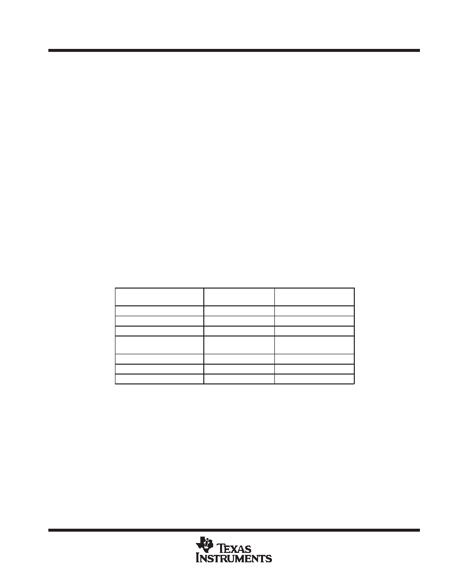
Three TMDS channels are used to receive RGB pixel data during active display time, DE = high. The same three
channels also receive control signals, HSYNC, VSYNC, and user defined control signals CTL[3:1]. These
control signals are received during inactive display or blanking-time. Blanking-time is when DE = low. The
following table maps the received input data to appropriate TMDS input channel in a DVI compliant system.
RECEIVED PIXEL DATA
ACTIVE DISPLAY DE = HIGH
INPUT CHANNEL
OUTPUT PINS
(VALID FOR DE = HIGH)
Red[7:0]
Channel – 2 (Rx2
±)
Green[7:0]
Channel – 1 (Rx1
±)
Blue[7:0]
Channel – 0 (Rx0
±)
RECEIVED CONTROL DATA
BLANKING DE = LOW
INPUT CHANNEL
OUTPUT PINS
(VALID FOR DE = LOW)
CTL[3:2]
Channel – 2 (Rx2
±)
CTL[3:2]
CTL[1: 0] (see Note 6)
Channel – 1 (Rx1
±)
CTL1
HSYNC, VSYNC
Channel – 0 (Rx0
±)
HSYNC, VSYNC
NOTE 7: Some TMDS transmitters transmit a CTL0 signal. The TFP9431 decodes and
transfers CTL[3:1] and ignores CTL0 characters. CTL0 is not available as a TFP9431
output.
The TFP9431 discriminates between valid pixel TMDS characters and control TMDS characters to determine
the state of active display versus blanking, i.e., state of DE.
相關PDF資料 |
PDF描述 |
|---|---|
| TG355ENK-7916 | 8.15 MHz, LOW PASS FILTER |
| TH355BDI-4957 | 4.43 MHz, BAND PASS FILTER |
| TH355LDK-7915 | 8.15 MHz, LOW PASS FILTER |
| TH355LNK-4550 | 10 MHz, LOW PASS FILTER |
| TH355LNK-4867 | 5 MHz, LOW PASS FILTER |
相關代理商/技術參數 |
參數描述 |
|---|---|
| TFP-AA-10T-13 | 制造商:DIALIGHT 制造商全稱:Dialight Corporation 功能描述:Tactical Composite Front Park Turn Light |
| TFPAA13B13 | 制造商:Dialight 功能描述: |
| TFPAA13D13 | 制造商:Dialight 功能描述: |
| TFPAA13T13 | 制造商:Dialight 功能描述: |
| TFP-AA-13T-13 | 制造商:DIALIGHT 制造商全稱:Dialight Corporation 功能描述:Tactical Composite Front Park Turn Light |
發布緊急采購,3分鐘左右您將得到回復。