- 您現在的位置:買賣IC網 > PDF目錄98255 > TLV320DAC3120IRHBT (TEXAS INSTRUMENTS INC) SERIAL INPUT LOADING, 24-BIT DAC, PQCC32 PDF資料下載
參數資料
| 型號: | TLV320DAC3120IRHBT |
| 廠商: | TEXAS INSTRUMENTS INC |
| 元件分類: | DAC |
| 英文描述: | SERIAL INPUT LOADING, 24-BIT DAC, PQCC32 |
| 封裝: | 5 X 5 MM, PLASTIC, QFN-32 |
| 文件頁數: | 33/110頁 |
| 文件大小: | 1230K |
| 代理商: | TLV320DAC3120IRHBT |
第1頁第2頁第3頁第4頁第5頁第6頁第7頁第8頁第9頁第10頁第11頁第12頁第13頁第14頁第15頁第16頁第17頁第18頁第19頁第20頁第21頁第22頁第23頁第24頁第25頁第26頁第27頁第28頁第29頁第30頁第31頁第32頁當前第33頁第34頁第35頁第36頁第37頁第38頁第39頁第40頁第41頁第42頁第43頁第44頁第45頁第46頁第47頁第48頁第49頁第50頁第51頁第52頁第53頁第54頁第55頁第56頁第57頁第58頁第59頁第60頁第61頁第62頁第63頁第64頁第65頁第66頁第67頁第68頁第69頁第70頁第71頁第72頁第73頁第74頁第75頁第76頁第77頁第78頁第79頁第80頁第81頁第82頁第83頁第84頁第85頁第86頁第87頁第88頁第89頁第90頁第91頁第92頁第93頁第94頁第95頁第96頁第97頁第98頁第99頁第100頁第101頁第102頁第103頁第104頁第105頁第106頁第107頁第108頁第109頁第110頁
1
0
1
HPF
15
1
N
N z
H
(z)
2
D z
-
+
=
-
1
0
1
LPF
15
1
N
N z
H
(z)
2
D z
-
+
=
-
www.ti.com
SLAS659 – NOVEMBER 2009
The VOL/MICDET pin connection and functionality are shown in Figure 1-1.
As shown in Table 5-13, the VOL/MICDET pin has a range of volume control from 18 dB down to –63 dB,
and mute. However, if less maximum gain is required, then a smaller range of voltage should be applied
to the VOL/MICDET pin. This can be done by increasing the value of R2 relative to the value of (P1 + R1),
so that more voltage is available at the bottom of P1. The circuit should also be designed such that for the
values of R1, R2, and P1 chosen, the maximum voltage (top of the potentiometer) does not exceed
AVDD/2 (see Figure 5-1). The recommended values for R1, R2, and P1 for several maximum gains are
shown in Table 5-14. Note that In typical applications, R1 should not be 0
, as the VOL/MICDET pin
should not exceed AVDD/2 for proper ADC operation.
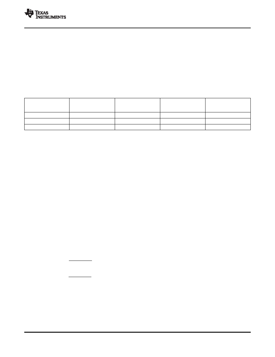
Table 5-14. VOL/MICDET Pin Gain Scaling
ADC VOLTAGE
R1
P1
R2
DIGITAL GAIN RANGE
for AVDD = 3.3 V
(k
)
(k
)
(k
)
(dB)
(V)
25
0
0 V to 1.65 V
18 dB to –63 dB
33
25
7.68
0.386 V to 1.642 V
3 dB to –63 dB
34.8
25
9.76
0.463 V to 1.649 V
0 dB to –63 dB
5.6.4
Dynamic Range Compression
Typical music signals are characterized by crest factors, the ratio of peak signal power to average signal
power, of 12 dB or more. To avoid audible distortions due to clipping of peak signals, the gain of the DAC
channel must be adjusted so as not to cause hard clipping of peak signals. As a result, during nominal
periods, the applied gain is low, causing the perception that the signal is not loud enough. To overcome
this problem, DRC in the TLV320DAC3120 continuously monitors the output of the DAC digital volume
control to detect its power level relative to 0 dBFS. When the power level is low, DRC increases the input
signal gain to make it sound louder. At the same time, if a peaking signal is detected, it autonomously
reduces the applied gain to avoid hard clipping. This results in sounds more pleasing to the ear as well as
sounding louder during nominal periods.
The DRC functionality in the TLV320DAC3120 is implemented by a combination of processing blocks in
the DAC channel as described in Section 5.6.1.2.
DRC can be disabled by writing to page 0 / register 68, bits D6–D5.
DRC typically works on the filtered version of the input signal. The input signals have no audio information
at dc and extremely low frequencies; however, they can significantly influence the energy estimation
function in DRC. Also, most of the information about signal energy is concentrated in the low-frequency
region of the input signal.
To estimate the energy of the input signal, the signal is first fed to the DRC high-pass filter and then to the
DRC low-pass filter. These filters are implemented as first-order IIR filters given by
(3)
(4)
The coefficients for these filters are 16 bits wide in 2s-complement format and are user-programmable
through register write as given in Table 5-15.
Copyright 2009, Texas Instruments Incorporated
APPLICATION INFORMATION
29
Product Folder Link(s): TLV320DAC3120
相關PDF資料 |
PDF描述 |
|---|---|
| TLV320DAC3202IYZJR | VOLUME CONTROL CIRCUIT, PBGA20 |
| TLV320DAC3202IYZJT | VOLUME CONTROL CIRCUIT, PBGA20 |
| TLV320DAC32IRHBR | SERIAL INPUT LOADING, DAC WITH PROGRAMMABLE PLL, PQCC32 |
| TLV320DAC32IRHBTG4 | SERIAL INPUT LOADING, DAC WITH PROGRAMMABLE PLL, PQCC32 |
| TLV320DAC32IRHBT | SERIAL INPUT LOADING, DAC WITH PROGRAMMABLE PLL, PQCC32 |
相關代理商/技術參數 |
參數描述 |
|---|---|
| TLV320DAC3120IRHBT | 制造商:Texas Instruments 功能描述:D/A Converter (D-A) IC 制造商:Texas Instruments 功能描述:IC, DAC, 32BIT, 192KSPS, QFN-32 |
| TLV320DAC32 | 制造商:BB 制造商全稱:BB 功能描述:LOW POWER STEREO AUDIO DAC FOR PORTABLE AUDIO/TELEPHONY |
| TLV320DAC3202 | 制造商:TI 制造商全稱:Texas Instruments 功能描述:LOW POWER HIGH FIDELITY I2S INPUT HEADSET IC |
| TLV320DAC3202BYZJR | 功能描述:音頻數/模轉換器 IC Lo Pwr Hi Fidelity I2S Input Headset IC RoHS:否 制造商:Texas Instruments 轉換器數量: 分辨率:16 bit 接口類型:I2S, UBS 轉換速率: 信噪比:98 dB 工作電源電壓:5 V DAC 輸出端數量:2 工作溫度范圍:- 25 C to + 85 C 電源電流:23 mA 安裝風格:SMD/SMT 封裝 / 箱體:TQFP-32 封裝:Reel |
| TLV320DAC3202CYZJR | 功能描述:音頻放大器 Low Pwr Hi Fidelity I2S Input Headset IC RoHS:否 制造商:STMicroelectronics 產品:General Purpose Audio Amplifiers 輸出類型:Digital 輸出功率: THD + 噪聲: 工作電源電壓:3.3 V 電源電流: 最大功率耗散: 最大工作溫度: 安裝風格:SMD/SMT 封裝 / 箱體:TQFP-64 封裝:Reel |
發布緊急采購,3分鐘左右您將得到回復。