- 您現在的位置:買賣IC網 > PDF目錄98285 > TPS65200YFFR (TEXAS INSTRUMENTS INC) 1-CHANNEL POWER SUPPLY SUPPORT CKT, BGA36 PDF資料下載
參數資料
| 型號: | TPS65200YFFR |
| 廠商: | TEXAS INSTRUMENTS INC |
| 元件分類: | 電源管理 |
| 英文描述: | 1-CHANNEL POWER SUPPLY SUPPORT CKT, BGA36 |
| 封裝: | 2.80 X 2.60 MM, 0.40 MM PITCH, GREEN, DSBGA-36 |
| 文件頁數: | 16/59頁 |
| 文件大小: | 2424K |
| 代理商: | TPS65200YFFR |
第1頁第2頁第3頁第4頁第5頁第6頁第7頁第8頁第9頁第10頁第11頁第12頁第13頁第14頁第15頁當前第16頁第17頁第18頁第19頁第20頁第21頁第22頁第23頁第24頁第25頁第26頁第27頁第28頁第29頁第30頁第31頁第32頁第33頁第34頁第35頁第36頁第37頁第38頁第39頁第40頁第41頁第42頁第43頁第44頁第45頁第46頁第47頁第48頁第49頁第50頁第51頁第52頁第53頁第54頁第55頁第56頁第57頁第58頁第59頁
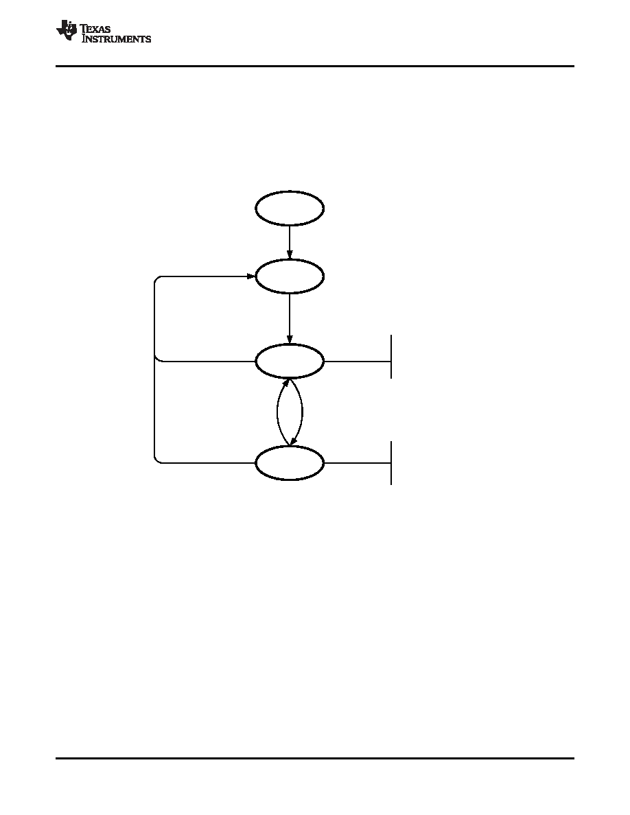
POWER DOWN
STANDBY
ACTIVE
VSYS>VUVLO, VSYS ||
VBUS>VUVLO, VBUS
LDO_EN = 1 ||
CH_EN_[1:0] != 00
Charger not HiZ||
WLED is ON||
Charger in HiZ mode&
WLED OFF
WLED driver= Disabled
LDO = OFF
CHARGER= HiZ
WLED driver= ON or
CHARGER= /HiZ
STARTUP
VBUS<VUVLO, VBUS &
VSYS<VUVLO, VSYS
|| = OR
& = AND
(
?) = rising edge
(
?) = falling edge
www.ti.com
SLVSA48 – APRIL 2010
GLOBAL STATE DIAGRAM
During normal operation TPS65200 is either in STANDBY mode or ACTIVE mode, depending on user inputs. In
STANDBY mode most functions are turned off to conserve power but the IC can still be accessed through I2C
bus and the current shunt monitor can be turned on and off. The bias system and main oscillator are turned off in
STANDBY mode.
The device enters ACTIVE mode whenever VBUS is asserted or the WLED driver is turned on. In ACTIVE mode
the main oscillator and reference system is turned on. The device will remain in ACTIVE mode as long as VBUS
remains high and/or the WLED driver is enabled.
Figure 43. Global State Diagram
LED DRIVER OPERATION
The TPS65200 offers a high efficiency, high output voltage boost converter designed for driving up to 10 white
LED in series. The serial LED connection provides even illumination by sourcing the same output current through
all LEDs, eliminating the need for expensive factory calibration. The device integrates 40-V/0.7-A switch FET and
operates in pulse width modulation (PWM) with 600-kHz fixed switching frequency. For operation see the block
diagram.
The LED driver can be enabled either through the CTRL pin or the WLED_EN bit in the CONTROL register. The
CTRL input is edge sensitive and should be pulled low at power-up. The CTRL pin allows PWM dimming of the
LEDs whereas the WLED_EN bit offers simple ON/OFF control only. The WLED_EN bit has priority over the
CTRL pin and when set to 1, the CTRL pin is ignored. If WLED_EN is set to 0 and the CTRL pin is low for
> 2.5 ms, the WLED driver is shut down.
The feedback loop regulates the FB pin voltage to the reference set by the VFB[4:0] bits in the WLED register
with a default setting of 200 mV. If any fault occurs during normal operation the driver is disabled, WLED_EN bit
is reset to 0 and the driver is put into FAULT state until the CTRL pin has been low for > 2.5 ms. The state
diagram for the WLED driver is shown in Figure 44.
Copyright 2010, Texas Instruments Incorporated
23
Product Folder Link(s): TPS65200
相關PDF資料 |
PDF描述 |
|---|---|
| TPS65251RHAT | SWITCHING REGULATOR, PQCC40 |
| TPS65251RHAR | SWITCHING REGULATOR, PQCC40 |
| TPS65257RHAT | 4 A SWITCHING REGULATOR, 2200 kHz SWITCHING FREQ-MAX, PQCC40 |
| TPS65510RGTRG4 | 1-CHANNEL POWER SUPPLY SUPPORT CKT, PQCC16 |
| TPS65510RGTTG4 | 1-CHANNEL POWER SUPPLY SUPPORT CKT, PQCC16 |
相關代理商/技術參數 |
參數描述 |
|---|---|
| TPS65200YFFT | 功能描述:PMIC 解決方案 Li+ Batt Chrgr RoHS:否 制造商:Texas Instruments 安裝風格:SMD/SMT 封裝 / 箱體:QFN-24 封裝:Reel |
| TPS65-201A-S | 功能描述:65MM RECTANGLE TRACKPAD 制造商:azoteq (pty) ltd 系列:IQ Switch?,ProxSense? 零件狀態:在售 傳感器類型:電容性 輸出類型:數字 工作溫度:0°C ~ 40°C 標準包裝:1 |
| TPS65203YFFR | 制造商:TI 功能描述:Ox Low End |
| TPS65217AEVM | 功能描述:電源管理IC開發工具 TPS65217A Eval Mod RoHS:否 制造商:Maxim Integrated 產品:Evaluation Kits 類型:Battery Management 工具用于評估:MAX17710GB 輸入電壓: 輸出電壓:1.8 V |
| TPS65217ARSLR | 功能描述:PMIC 解決方案 Sgl Chip Pwr Sol RoHS:否 制造商:Texas Instruments 安裝風格:SMD/SMT 封裝 / 箱體:QFN-24 封裝:Reel |
發布緊急采購,3分鐘左右您將得到回復。