- 您現在的位置:買賣IC網 > PDF目錄374037 > ADSP-21MOD980N (Analog Devices, Inc.) MultiPort Internet Gateway Processor PDF資料下載
參數資料
| 型號: | ADSP-21MOD980N |
| 廠商: | Analog Devices, Inc. |
| 英文描述: | MultiPort Internet Gateway Processor |
| 中文描述: | 通寶互聯網網關處理器 |
| 文件頁數: | 12/42頁 |
| 文件大小: | 566K |
| 代理商: | ADSP-21MOD980N |
第1頁第2頁第3頁第4頁第5頁第6頁第7頁第8頁第9頁第10頁第11頁當前第12頁第13頁第14頁第15頁第16頁第17頁第18頁第19頁第20頁第21頁第22頁第23頁第24頁第25頁第26頁第27頁第28頁第29頁第30頁第31頁第32頁第33頁第34頁第35頁第36頁第37頁第38頁第39頁第40頁第41頁第42頁
12
6/2001
REV. PrB
For current information contact Analog Devices at (800) ANALOGD
ADSP-21mod980N
PRELIMINARY TECHNICAL DATA
SLAVE MODE
This section describes the Slave Mode memory configura-
tion of the Modem Processors.
INTERNAL MEMORY DMA PORT (IDMA PORT)
The IDMA Port provides an efficient way for a host system
and the ADSP-21mod980N to communicate. The port is
used to access the on-chip program memory and data mem-
ory of each modem processor with only one processor cycle
per word overhead. The IDMA port cannot be used, how-
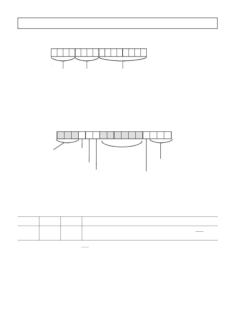
Figure 7. Programmable Flag
1
& Composite Select Control Register
1
Since they are multiplexed within the ADSP-21mod980N, PF[2:0] should be configured as an output for only one processor at a time. Bit [3] of DM
(0x3FE6) must also be 0 to ensure that PF[3] is never an output.
15
14
13
12
11
10
9
8
7
6
5
4
3
2
1
0
1
1
1
1
1
0
1
1
0
0
0
0
0
0
0
0
DM(0x3FE6)
PFTYPE
0 = Input
1 = Output
CMSSEL
0 = Disable CMS
1 = Enable CMS
(where bit: 11-IOM, 10-BM, 9-DM, 8-PM)
BMWAIT
Figure 8. System Control Register
15
14
13
12
11
10
9
8
7
6
5
4
3
2
1
0
0
0
0
0
0
1
0
0
0
1
1
1
0
0
0
0
SPORT1 Enable
0 = Disable
1 = Enable
PWAIT
Program Memory
Wait States
SPORT1 Configure
0 = FI, FO, IRQ0, IRQ1, SCLK
1= SPORT1
Disable BMS
0 = Enable BMS
1 = Disable BMS, except when
memory strobes are three-stated
SPORT0 Enable
0 = Disable
1 = Enable
DM(0x3FFF)
RESERVED
SET TO 0
Reserved Set
To 0
Table 6. ADSP-21mod980N Mode of Operation
MODE C
MODE B
MODE A
Booting Method
1
0
1
IDMA feature is used to load internal memory as desired. Program execution is held off until internal
program memory location 0x0000 is written to. Chip is configured in Slave Mode.
1
IACK requires
external pulldown.
2
1
Considered standard operating settings. These configurations simplify your design and improve memory management.
2
IDMA timing details and the correct usage of IACK are described in the
ADSP-2100 Family User’s Manual
.
相關PDF資料 |
PDF描述 |
|---|---|
| ADSP-21MOD980N-000 | CAP 27PF 100V 10% X7R AXIAL BULK M-MIL-PRF-39014 |
| ADSP-21MSP58BST-104 | DSP Microcomputers |
| ADSP-BF531 | Blackfin Embedded Processor |
| ADSP-BF531SBBC400 | Metal Connector Backshell |
| ADSP-BF531SBBZ400 | Blackfin Embedded Processor |
相關代理商/技術參數 |
參數描述 |
|---|---|
| ADSP-21MSP50ABG-52 | 制造商:Analog Devices 功能描述: |
| adsp-21msp50akg-52 | 制造商:Rochester Electronics LLC 功能描述:- Bulk 制造商:Analog Devices 功能描述: |
| ADSP-21MSP50BG-52 | 制造商:Rochester Electronics LLC 功能描述:- Bulk |
| ADSP-21MSP50KG-52 | 制造商:Rochester Electronics LLC 功能描述:- Bulk |
| ADSP-21MSP52-520010 | 制造商:Analog Devices 功能描述: |
發布緊急采購,3分鐘左右您將得到回復。