- 您現在的位置:買賣IC網 > PDF目錄374037 > ADSP-21MOD980N (Analog Devices, Inc.) MultiPort Internet Gateway Processor PDF資料下載
參數資料
| 型號: | ADSP-21MOD980N |
| 廠商: | Analog Devices, Inc. |
| 英文描述: | MultiPort Internet Gateway Processor |
| 中文描述: | 通寶互聯網網關處理器 |
| 文件頁數: | 6/42頁 |
| 文件大小: | 566K |
| 代理商: | ADSP-21MOD980N |
第1頁第2頁第3頁第4頁第5頁當前第6頁第7頁第8頁第9頁第10頁第11頁第12頁第13頁第14頁第15頁第16頁第17頁第18頁第19頁第20頁第21頁第22頁第23頁第24頁第25頁第26頁第27頁第28頁第29頁第30頁第31頁第32頁第33頁第34頁第35頁第36頁第37頁第38頁第39頁第40頁第41頁第42頁
6
6/2001
REV. PrB
For current information contact Analog Devices at (800) ANALOGD
ADSP-21mod980N
PRELIMINARY TECHNICAL DATA
MEMORY INTERFACE PINS
The ADSP-21mod980N modem pool is used in Slave
Mode. In Slave Mode, the Modem Processors operate in
host configuration. The operating mode is determined by
the state of the Mode C pin during RESET and cannot be
changed while the modem pool is running. See the
“
Mem-
ory Architecture
”
section for more information.
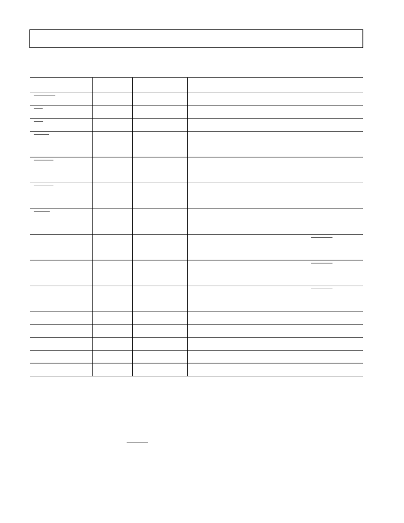
Table 1. Common Mode Pins
Pin Name(s)
# of Pins
Input/Output
Function
RESET
8
I
Processor Reset Input
BR
8
I
Bus Request Input
BG
8
O
Bus Grant Output
IRQ2 /
8
I
Edge- or Level-Sensitive Interrupt Request
1
PF7
8
I/O
Programmable I/O Pin
IRQL1 /
8
I
Level-Sensitive Interrupt Requests
1
PF6
8
I/O
Programmable I/O Pin
IRQL0 /
8
I
Level-Sensitive Interrupt Requests
1
PF5
8
I/O
Programmable I/O Pin
IRQE /
8
I
Edge-Sensitive Interrupt Requests
1
PF4
8
I/O
Programmable I/O Pin
Mode C /
1
I
Mode Select Input - Checked Only During RESET
PF2
1
I/O
Programmable I/O Pin During Normal Operation
Mode B /
1
I
Mode Select Input - Checked Only During RESET
PF1
1
I/O
Programmable I/O Pin During Normal Operation
Mode A /
1
I
Mode Select Input - Checked Only During RESET
PF0
1
I/O
Programmable I/O Pin During Normal Operation
CLKIN
1
I
Clock Input
CLKOUT
8
O
Processor Clock Output
SPORT
28
I/O
Serial Port I/O Pins
2
V
DD
and GND
175
I
Power and Ground
EZ-Port
16
I/O
For Emulation Use
1
Interrupt/Flag Pins retain both functions concurrently. If IMASK is set to enable the corresponding interrupts, then the ADSP-21mod980N will vector
to the appropriate interrupt vector address when the pin is asserted, either by external devices, or set as a programmable flag.
2
SPORT configuration determined by the ADSP-21mod980N System Control Register. Software configurable.
相關PDF資料 |
PDF描述 |
|---|---|
| ADSP-21MOD980N-000 | CAP 27PF 100V 10% X7R AXIAL BULK M-MIL-PRF-39014 |
| ADSP-21MSP58BST-104 | DSP Microcomputers |
| ADSP-BF531 | Blackfin Embedded Processor |
| ADSP-BF531SBBC400 | Metal Connector Backshell |
| ADSP-BF531SBBZ400 | Blackfin Embedded Processor |
相關代理商/技術參數 |
參數描述 |
|---|---|
| ADSP-21MSP50ABG-52 | 制造商:Analog Devices 功能描述: |
| adsp-21msp50akg-52 | 制造商:Rochester Electronics LLC 功能描述:- Bulk 制造商:Analog Devices 功能描述: |
| ADSP-21MSP50BG-52 | 制造商:Rochester Electronics LLC 功能描述:- Bulk |
| ADSP-21MSP50KG-52 | 制造商:Rochester Electronics LLC 功能描述:- Bulk |
| ADSP-21MSP52-520010 | 制造商:Analog Devices 功能描述: |
發布緊急采購,3分鐘左右您將得到回復。