- 您現在的位置:買賣IC網 > PDF目錄382738 > Z684 FUSE 3A/125V SUB-MINIATURE PICO PDF資料下載
參數資料
| 型號: | Z684 |
| 英文描述: | FUSE 3A/125V SUB-MINIATURE PICO |
| 中文描述: | 控制器雜項-數據表參考 |
| 文件頁數: | 7/13頁 |
| 文件大小: | 129K |
| 代理商: | Z684 |

––––––––––––––––––––––––––––––––––––––––––––––––––––––––––––––––––––––
I
Z684 PCI Bus Controller
I
7
OKI SEMICONDUCTOR
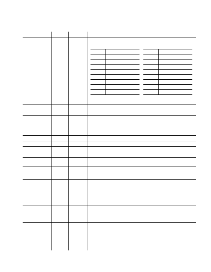
ICBEB[3:0]
Input
–
Command and Byte Enable Bus
bus inputs with the PCI command definitions shown below.
. These are the PCI multiplexed command and byte enable
EDEVSELB
Output
LOW
Device Select Enable
. The EDEVSELB signal is the enable output for the PCI DEVSEL# signal.
EFRAMEB
Output
LOW
Frame Enable
. The EFRAMEB signal is the enable output for the PCI FRAME# pin.
EIRDYB
Output
LOW
Initiator Data Ready Enable
. The EIRDYB signal is the enable output for the PCI IRDY# pin.
ELOCKB
Output.
LOW
Lock Enable
. The ELOCKB signal is the enable output for the PCI LOCK# pin.
ESTOPB
Output
LOW
Transaction Stop/Retry Enable
pin.
. The ESTOPB signal is the enable output for the PCI STOP#
ETRDYB
Output
LOW
Target Data Ready Enable
. The ETRDYB signal is the enable output for the PCI TRDY# pin.
EPAR
Output
LOW
Parity Enable
. The EPAR signal is the enable output for the PCI PAR pin.
EPERRB
Output
LOW
Parity Error Enable
. The EPERRB signal is the enable output for the PCI PERR# pin.
ESERRB
Output
LOW
System Error Enable
. The ESERRB signal is the enable output for the PCI SERR# pin.
EAD
Output
LOW
Address and Data Bus Enable
. The EAD signal is the enable output for the PCI AD[31:0] pins.
ECBEB
Output
LOW
Command and Byte Enable Bus Enable
CBE#[3:0] pins.
. The ECBEB is the enable output for the PCI
ODEVSELB
Output
LOW
Device Select Output
target PCI bus device for access. The ODEVSELB signal is the output pin for the PCI DEVSEL#
signal.
. The ODEVSELB signal indicates that the Z684 has been selected as a
OFRAMEB
Output
LOW
Frame Output
The OFRAMEB signal is deasserted before the last data phase of the current transaction. The
OFRAMEB signal is the output pin for the PCI FRAME# signal.
. The OFRAMEB signal indicates the beginning and duration of a transaction.
OIRDYB
Output
LOW
Initiator Data Ready
indicates the initiator's ability to complete the current data phase. The OIRDYB signal is the
output pin for the PCI IRDY# signal.
. When the Z684 drives the OIRDYB output low, the OIRDYB signal
OLOCKB
Output
LOW
LOCKb Output
transactions to complete. The OLOCKB signal is the output signal for the PCI LOCK# pin and
is driven by the Z684. The OLOCKB signal is only used when system memory is supported.
This pin is not supported in the current Z684 version and must be tied inactive (HIGH).
. The OLOCKB signal indicates an atomic operation that may require multiple
OSTOPB
Output
LOW
Stop/Retry Output
current transaction. The OSTOPB signal is the output for the PCI STOP# pin.
. The OSTOPB indicates that the Z684 is requesting the initiator to stop the
OTRDYB
Output
LOW
TRDYb Output
phase of the transaction. The OTRDYB pin is the output signal for the PCI TRDY# pin.
. This signal indicates the target device's ability to complete the current data
OPAR
Output
–
Parity
buses. The OPAR pin is the output signal for the PCI PAR pin.
. The OPAR signal is an even parity output across the PCI address/data and byte enable
PCI Interface Signals
(Continued)
Signal
Type
Assertion
Description
ICBEB[3:0]
Command Type
0000
Interrupt Acknowledge
0001
Special Cycle
0010
I/O Read
0011
I/O Write
0100
Reserved
0101
Reserved
0110
Memory Read
0111
Memory Write
ICBEB[3:0]
Command Type
1000
Reserved
1001
Reserved
1010
Configuration Read
1011
Configuration Write
1100
Memory Read Multiple
1101
Dual Access Cycle
1110
Memory Read Line
1111
Memory Write and Invalidate
相關PDF資料 |
PDF描述 |
|---|---|
| Z706LR | Automotive Fuse; Current Rating:20A; Voltage Rating:32V; Fuse Type:Fast Acting; Fuse Terminals:Blade; Length:18.54mm; Series:257; Fuse Size/Group:18.54 x 19.05 x 5.08mm |
| Z706R | TRANSFORMER VARI.ENCLOSED 6A |
| Z708R | TRANSFORMER VARI.ENCLOSED 8A |
| Z710R | Leaded Cartridge Fuse; Current Rating:2mA; Voltage Rating:125V; Fuse Terminals:Radial Lead; Fuse Type:Fast Acting; Voltage Rating:125V; Body Material:Epoxy; Diameter:6.35mm; Leaded Process Compatible:No; Length:8.89mm RoHS Compliant: No |
| Z706 | Automotive Fuse; Current Rating:3A; Voltage Rating:32V; Fuse Type:Fast Acting; Fuse Terminals:Blade; Length:18.54mm; Series:257; Fuse Size/Group:18.54 x 19.05 x 5.08mm |
相關代理商/技術參數 |
參數描述 |
|---|---|
| Z68726 | 制造商:ITT Interconnect Solutions 功能描述:Z68726 - Bulk |
| Z68E11 | 制造商:OMRON INDUSTRIAL AUTOMATION 功能描述:V620 SERIAL SYSTEM MANUAL DX CODE ZA |
| Z6950700 | 制造商:Jewell Instruments 功能描述:ANALOG PANEL METER MODEL 321HR RANGE 0-50MVDC SCALE 0-40ADC |
| Z69702 | 制造商:ITT Interconnect Solutions 功能描述: |
| Z69E11 | 制造商:OMRON INDUSTRIAL AUTOMATION 功能描述:V620 PARALLEL SYSTEM MANUAL DX CODE ZA |
發布緊急采購,3分鐘左右您將得到回復。