- 您現(xiàn)在的位置:買賣IC網(wǎng) > PDF目錄250212 > 70V659S15DR (INTEGRATED DEVICE TECHNOLOGY INC) 128K X 36 DUAL-PORT SRAM, 15 ns, PQFP208 PDF資料下載
參數(shù)資料
| 型號(hào): | 70V659S15DR |
| 廠商: | INTEGRATED DEVICE TECHNOLOGY INC |
| 元件分類: | SRAM |
| 英文描述: | 128K X 36 DUAL-PORT SRAM, 15 ns, PQFP208 |
| 封裝: | 28 X 28 MM, 3.50 MM HEIGHT, PLASTIC, QFP-208 |
| 文件頁(yè)數(shù): | 11/24頁(yè) |
| 文件大小: | 316K |
| 代理商: | 70V659S15DR |
第1頁(yè)第2頁(yè)第3頁(yè)第4頁(yè)第5頁(yè)第6頁(yè)第7頁(yè)第8頁(yè)第9頁(yè)第10頁(yè)當(dāng)前第11頁(yè)第12頁(yè)第13頁(yè)第14頁(yè)第15頁(yè)第16頁(yè)第17頁(yè)第18頁(yè)第19頁(yè)第20頁(yè)第21頁(yè)第22頁(yè)第23頁(yè)第24頁(yè)
19
IDT70V659/58/57S
High-Speed 3.3V 128/64/32K x 36 Asynchronous Dual-Port Static RAM
Industrial and Commercial Temperature Ranges
Functional Description
The IDT70V659/58/57 provides two ports with separate control,
addressandI/Opinsthatpermitindependentaccessforreadsorwrites
toanylocationinmemory.TheIDT70V659/58/57hasanautomaticpower
down feature controlled by CE. The CE0 and CE1 control the on-chip
powerdowncircuitrythatpermitstherespectiveporttogointoastandby
mode when not selected (CE = HIGH). When a port is enabled, access
to the entire memory array is permitted.
Interrupts
Iftheuserchoosestheinterruptfunction,amemorylocation(mail box
or message center) is assigned to each port. The left port interrupt flag
(INTL) is asserted when the right port writes to memory location 1FFFE
(HEX) (FFFE for IDT70V658 and 7FFE for IDT70V657), where a write
isdefinedasCER=R/WR=VILpertheTruthTableIII.Theleftportclears
the interrupt through access of address location 1FFFE (FFFE for
IDT70V658 and 7FFE for IDT70V657) when CEL = OEL = VIL, R/W is
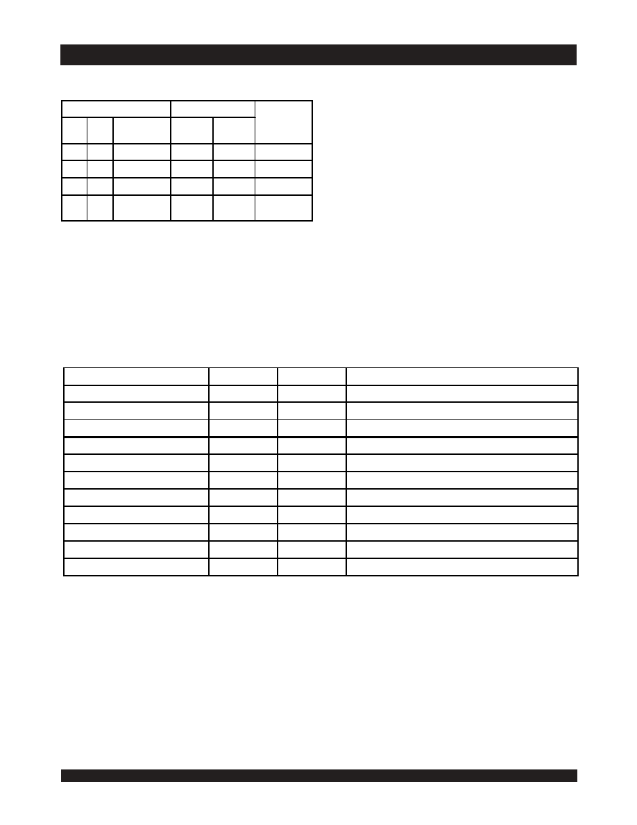
Truth Table IV —
Address BUSY Arbitration
NOTES:
1. Pins BUSYL and BUSYR are both outputs when the part is configured as a master. Both are inputs when configured as a slave. BUSY outputs on the
IDT70V659/58/57 are push-pull, not open drain outputs. On slaves the BUSY input internally inhibits writes.
2. "L" if the inputs to the opposite port were stable prior to the address and enable inputs of this port. "H" if the inputs to the opposite port became stable after the address
and enable inputs of this port. If tAPS is not met, either BUSYL or BUSYR = LOW will result. BUSYL and BUSYR outputs can not be LOW simultaneously.
3. Writes to the left port are internally ignored when BUSYL outputs are driving LOW regardless of actual logic level on the pin. Writes to the right port are internally ignored
when BUSYR outputs are driving LOW regardless of actual logic level on the pin.
4. A16X is a NC for IDT70V658, therefore Address comparison will be for A0 - A15. Also, A16X and A15X are NC's for IDT70V657, therefore Address comparison will
be for A0 - A14.
Inputs
Outputs
Function
CEL
CER
AOL-A16L(4)
AOR-A16R
BUSYL(1)
BUSYR(1)
X
NO MATCH
H
Normal
H
X
MATCHH
HNormal
X
H
MATCHH
HNormal
LL
MATCH
(2)
Write Inhibit(3)
4869 tbl 17
Truth Table V — Example of Semaphore Procurement Sequence(1,2,3)
NOTES:
1. This table denotes a sequence of events for only one of the eight semaphores on the IDT70V659/58/57.
2. There are eight semaphore flags written to via I/O0 and read from all I/O's (I/O0-I/O35). These eight semaphores are addressed by A0 - A2.
3. CE = VIH, SEM = VIL to access the semaphores. Refer to the Semaphore Read/Write Control Truth Table.
Functions
D0 - D35 Left
D0 - D35 Right
Status
No Action
1
Semaphore free
Left Port Writes "0" to Semaphore
0
1
Left port has semaphore token
Right Port Writes "0" to Semaphore
0
1
No change. Right side has no write access to semaphore
Left Port Writes "1" to Semaphore
1
0
Right port obtains semaphore token
Left Port Writes "0" to Semaphore
1
0
No change. Left port has no write access to semaphore
Right Port Writes "1" to Semaphore
0
1
Left port obtains semaphore token
Left Port Writes "1" to Semaphore
1
Semaphore free
Right Port Writes "0" to Semaphore
1
0
Right port has semaphore token
Right Port Writes "1" to Semaphore
1
Semaphore free
Left Port Writes "0" to Semaphore
0
1
Left port has semaphore token
Left Port Writes "1" to Semaphore
1
Semaphore free
4869 tbl 18
相關(guān)PDF資料 |
PDF描述 |
|---|---|
| 7P12FLV250I25 | 6M X 16 FLASH 3V PROM CARD, 250 ns, XMA68 |
| 7P12FLV281C15 | 6M X 16 FLASH 3V PROM CARD, 150 ns, XMA68 |
| 7P12FLV512C25 | 6M X 16 FLASH 3V PROM CARD, 250 ns, XMA68 |
| 7P12FLV552I25 | 6M X 16 FLASH 3V PROM CARD, 250 ns, XMA68 |
| 7P12FLV572I15 | 6M X 16 FLASH 3V PROM CARD, 150 ns, XMA68 |
相關(guān)代理商/技術(shù)參數(shù) |
參數(shù)描述 |
|---|---|
| 70V659S15DRI | 制造商:Integrated Device Technology Inc 功能描述:SRAM ASYNC DUAL 3.3V 4.5MBIT 128KX36 15NS 208PQFP - Bulk |
| 70V7319S133BC | 功能描述:IC SRAM 4.5MBIT 133MHZ 256CABGA 制造商:idt, integrated device technology inc 系列:- 包裝:托盤 零件狀態(tài):有效 格式 - 存儲(chǔ)器:RAM 存儲(chǔ)器類型:SRAM - 雙端口,同步 存儲(chǔ)容量:4.5M(256K x 18) 速度:133MHz 接口:并聯(lián) 電壓 - 電源:3.15 V ~ 3.45 V 工作溫度:0°C ~ 70°C(TA) 封裝/外殼:256-LBGA 供應(yīng)商器件封裝:256-CABGA(17x17) 標(biāo)準(zhǔn)包裝:6 |
| 70V7319S133BC8 | 功能描述:IC SRAM 4.5MBIT 133MHZ 256CABGA 制造商:idt, integrated device technology inc 系列:- 包裝:帶卷(TR) 零件狀態(tài):有效 格式 - 存儲(chǔ)器:RAM 存儲(chǔ)器類型:SRAM - 雙端口,同步 存儲(chǔ)容量:4.5M(256K x 18) 速度:133MHz 接口:并聯(lián) 電壓 - 電源:3.15 V ~ 3.45 V 工作溫度:0°C ~ 70°C(TA) 封裝/外殼:256-LBGA 供應(yīng)商器件封裝:256-CABGA(17x17) 標(biāo)準(zhǔn)包裝:1,000 |
| 70V7319S133BF | 功能描述:靜態(tài)隨機(jī)存取存儲(chǔ)器 RoHS:否 制造商:IDT 存儲(chǔ)容量: 組織: 訪問(wèn)時(shí)間: 電源電壓-最大: 電源電壓-最小: 最大工作電流: 最大工作溫度: 最小工作溫度: 安裝風(fēng)格: 封裝 / 箱體: 封裝: |
| 70V7319S133BF8 | 制造商:Integrated Device Technology Inc 功能描述:SRAM SYNC DUAL 3.3V 4.5MBIT 256KX18 15NS/4.2NS 208FBGA - Tape and Reel |
發(fā)布緊急采購(gòu),3分鐘左右您將得到回復(fù)。