- 您現在的位置:買賣IC網 > PDF目錄373970 > AD9910_07 (Analog Devices, Inc.) 1 GSPS, 14-Bit, 3.3 V CMOS Direct Digital Synthesizer PDF資料下載
參數資料
| 型號: | AD9910_07 |
| 廠商: | Analog Devices, Inc. |
| 元件分類: | XO, clock |
| 英文描述: | 1 GSPS, 14-Bit, 3.3 V CMOS Direct Digital Synthesizer |
| 中文描述: | 1 GSPS的,14位,3.3伏的CMOS直接數字頻率合成 |
| 文件頁數: | 30/60頁 |
| 文件大小: | 764K |
| 代理商: | AD9910_07 |
第1頁第2頁第3頁第4頁第5頁第6頁第7頁第8頁第9頁第10頁第11頁第12頁第13頁第14頁第15頁第16頁第17頁第18頁第19頁第20頁第21頁第22頁第23頁第24頁第25頁第26頁第27頁第28頁第29頁當前第30頁第31頁第32頁第33頁第34頁第35頁第36頁第37頁第38頁第39頁第40頁第41頁第42頁第43頁第44頁第45頁第46頁第47頁第48頁第49頁第50頁第51頁第52頁第53頁第54頁第55頁第56頁第57頁第58頁第59頁第60頁
AD9910
Rev. 0 | Page 30 of 60
DRG OUTPUT
LOWER LIMIT
UPPER LIMIT
DRCTL
DRHOLD
AUTOCLEAR DIGITAL
RAMP ACCUMULATOR
CLEAR DIGITAL
RAMP ACCUMULATOR
I/O_UPDATE
POSITIVE
STEP SIZE
NEGATIVE
STEP SIZE
P DDS CLOCK CYCLES
N DDS CLOCK CYCLES
1 DDS CLOCK CYCLE
DIGITAL RAMP ENABLE
DROVER
0
C
R
A
C
–
Δ
t
+
Δ
t
1
2
3
4
5
6
7
8
9
10
11
12
13
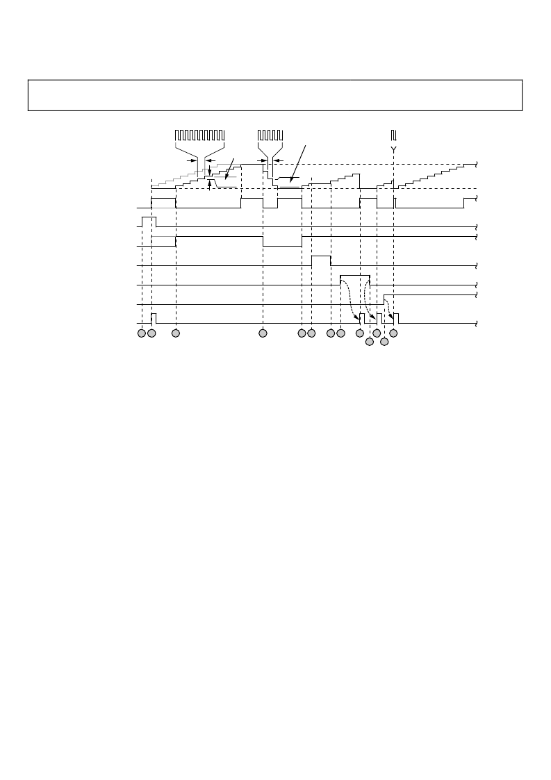
Figure 39. Normal Ramp Generation
Event 1—The digital ramp enable bit is set, which has no affect
on the DRG because the bit is not effective until an I/O update.
Event 2—An I/O update registers the enable bit. If DRCTL = 1
is in effect at this time (gray portion of DRCTL trace), then the
DRG output immediately begins a positive slope (gray portion
of DRG output trace). Otherwise, if DRCTL = 0, the DRG
output is initialized to the lower limit.
Event 3—DRCTL transitions to a Logic 1 to initiate a positive
slope at the DRG output. In this example, the DRCTL pin is
held long enough to cause the DRG to reach its programmed
upper limit. The DRG remains at the upper limit until the ramp
accumulator is cleared, DRCTL = 0, or the upper limit is
reprogrammed to a higher value. In the last case, the DRG
immediately resumes its previous positive slope profile.
Event 4—DRCTL transitions to a Logic 0 to initiate a negative
slope at the DRG output. In this example, the DRCTL pin is
held long enough to cause the DRG to reach its programmed
lower limit. The DRG remains at the lower limit until DRCTL = 1,
or the lower limit is reprogrammed to a lower value. In the
latter case, the DRG immediately resumes its previous negative
slope profile.
Event 5—DRCTL transitions to a Logic 1 for the second time,
initiating a second positive slope.
Event 6—The positive slope profile is interrupted by DRHOLD
transitioning to a Logic 1. This stalls the ramp accumulator and
freezes the DRG output at its last value.
Event 7—DRCTL transitions to a Logic 0, releasing the ramp
accumulator and reinstating the previous positive slope profile.
Event 8—The clear digital ramp accumulator bit is set, which
has no affect on the DRG because the bit is not effective until an
I/O update.
Event 9—An I/O update registers that the clear digital ramp
accumulator bit is set, resetting the ramp accumulator and
forcing the DRG output to the programmed lower limit. The
DRG output remains at the lower limit until the clear condition
is removed.
Event 10—The clear digital ramp accumulator bit is cleared,
which has no affect on the DRG because the bit is not effective
until an I/O update.
Event 11—An I/O update registers that the clear digital ramp
accumulator bit is cleared, releasing the ramp accumulator and
the previous positive slope profile restarts.
Event 12—The autoclear digital ramp accumulator bit is set,
which has no affect on the DRG because the bit is not effective
until an I/O update.
Event 13—An I/O update registers that the autoclear digital
ramp accumulator bit is set, resetting the ramp accumulator.
However, with an automatic clear, the ramp accumulator is only
held reset for a single DDS clock cycle. This forces the DRG
output to the lower limit, but the ramp accumulator is
immediately made available for normal operation. In this
example, the DRCTL pin remains a Logic 1, so the DRG output
restarts the previous positive ramp profile.
相關PDF資料 |
PDF描述 |
|---|---|
| AD9910BSVZ | 1 GSPS, 14-Bit, 3.3 V CMOS Direct Digital Synthesizer |
| AD9910BSVZ-REEL | 1 GSPS, 14-Bit, 3.3 V CMOS Direct Digital Synthesizer |
| AD9912 | 1 GSPS Direct Digital Synthesizer w/ 14-bit DAC |
| AD9913 | Low Power 250 MSPS 10-Bit DAC 1.8 V CMOS Direct Digital Synthesizer |
| AD9913BCPZ1 | Low Power 250 MSPS 10-Bit DAC 1.8 V CMOS Direct Digital Synthesizer |
相關代理商/技術參數 |
參數描述 |
|---|---|
| AD9910BSVZ | 功能描述:IC DDS 1GSPS 14BIT PAR 100TQFP RoHS:是 類別:集成電路 (IC) >> 接口 - 直接數字合成 (DDS) 系列:- 產品變化通告:Product Discontinuance 27/Oct/2011 標準包裝:2,500 系列:- 分辨率(位):10 b 主 fclk:25MHz 調節字寬(位):32 b 電源電壓:2.97 V ~ 5.5 V 工作溫度:-40°C ~ 85°C 安裝類型:表面貼裝 封裝/外殼:16-TSSOP(0.173",4.40mm 寬) 供應商設備封裝:16-TSSOP 包裝:帶卷 (TR) |
| AD9910BSVZ | 制造商:Analog Devices 功能描述:IC DDS 1GHZ TQFP-100 制造商:Analog Devices 功能描述:IC, DDS, 1GHZ, TQFP-100 |
| AD9910BSVZ-REEL | 功能描述:IC DDS 1GSPS 14BIT PAR 100TQFP RoHS:是 類別:集成電路 (IC) >> 接口 - 直接數字合成 (DDS) 系列:- 產品變化通告:Product Discontinuance 27/Oct/2011 標準包裝:2,500 系列:- 分辨率(位):10 b 主 fclk:25MHz 調節字寬(位):32 b 電源電壓:2.97 V ~ 5.5 V 工作溫度:-40°C ~ 85°C 安裝類型:表面貼裝 封裝/外殼:16-TSSOP(0.173",4.40mm 寬) 供應商設備封裝:16-TSSOP 包裝:帶卷 (TR) |
| AD9911 | 制造商:AD 制造商全稱:Analog Devices 功能描述:500 MSPS Direct Digital Synthesizer with 10-Bit DAC |
| AD9911/PCB | 制造商:Analog Devices 功能描述:500 MSPS DIRECT DGTL SYNTHESIZER W/ 10-BIT DAC AD9911/PCB - Bulk |
發布緊急采購,3分鐘左右您將得到回復。