- 您現在的位置:買賣IC網 > PDF目錄374044 > ADUuC7027BSTZ62-RL (Analog Devices, Inc.) Precision Analog Microcontroller 12-bit Analog I/O, ARM7TDMI MCU PDF資料下載
參數資料
| 型號: | ADUuC7027BSTZ62-RL |
| 廠商: | Analog Devices, Inc. |
| 英文描述: | Precision Analog Microcontroller 12-bit Analog I/O, ARM7TDMI MCU |
| 中文描述: | 精密模擬微控制器的12位模擬I / O,ARM7TDMI的微控制器 |
| 文件頁數: | 56/92頁 |
| 文件大小: | 850K |
| 代理商: | ADUUC7027BSTZ62-RL |
第1頁第2頁第3頁第4頁第5頁第6頁第7頁第8頁第9頁第10頁第11頁第12頁第13頁第14頁第15頁第16頁第17頁第18頁第19頁第20頁第21頁第22頁第23頁第24頁第25頁第26頁第27頁第28頁第29頁第30頁第31頁第32頁第33頁第34頁第35頁第36頁第37頁第38頁第39頁第40頁第41頁第42頁第43頁第44頁第45頁第46頁第47頁第48頁第49頁第50頁第51頁第52頁第53頁第54頁第55頁當前第56頁第57頁第58頁第59頁第60頁第61頁第62頁第63頁第64頁第65頁第66頁第67頁第68頁第69頁第70頁第71頁第72頁第73頁第74頁第75頁第76頁第77頁第78頁第79頁第80頁第81頁第82頁第83頁第84頁第85頁第86頁第87頁第88頁第89頁第90頁第91頁第92頁
ADuC7019/20/21/22/24/25/26/27
The advantage of double update mode is that lower harmonic
voltages can be produced by the PWM process and faster
control bandwidths are possible. However, for a given PWM
switching frequency, the PWMSYNC pulses occur at twice the
rate in the double update mode. Because new duty cycle values
must be computed in each PWMSYNC interrupt service
routine, there is a larger computational burden on the ARM
core in double update mode.
Rev. A | Page 56 of 92
PWM Duty Cycles (PWMCH0, PWMCH1,
PWMCH2 MMRs)
The duty cycles of the six PWM output signals on Pin PWM0
H
to Pin PWM2
L
are controlled by the three, 16-bit read/write
duty cycle registers, PWMCH0, PWMCH1, and PWMCH2.
The duty cycle registers are programmed in integer counts of
the fundamental time unit,
t
CORE
. They define the desired on-
time of the high-side PWM signal produced by the three-phase
timing unit over half the PWM period. The switching signals
produced by the three-phase timing unit are also adjusted to
incorporate the programmed dead time value in the
PWMDAT1 register. The three-phase timing unit produces
active low signals so that a low level corresponds to a command
to turn on the associated power device.
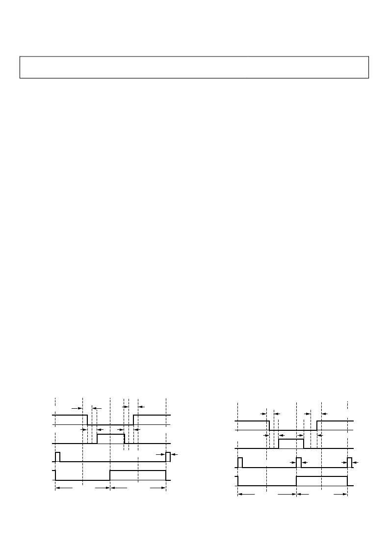
Figure 57 shows a typical pair of PWM outputs (in this case, 0H
and 0L) from the timing unit in single update mode. All
illustrated time values indicate the integer value in the
associated register and can be converted to time by simply
multiplying by the fundamental time increment,
t
CORE
. Note that
the switching patterns are perfectly symmetrical about the
midpoint of the switching period in this mode because the same
values of PWMCH0, PWMDAT0, and PWMDAT1 are used to
define the signals in both half cycles of the period.
Figure 57 also demonstrates how the programmed duty cycles
are adjusted to incorporate the desired dead time into the
resulting pair of PWM signals. Clearly, the dead time is incor-
porated by moving the switching instants of both PWM signals
(0H and 0L) away from the instant set by the PWMCH0 register.
0
–PWMDAT0/2
0H
0L
PWMSYNC
PWMSTA (0)
PWMDAT0
+PWMDAT0/2
–PWMDAT0/2
0
0
PWMDAT0
PWMDAT2+1
PWMCH0
2 × PWMDAT1
2 × PWMDAT1
PWMCH0
Figure 57. Typical PWM Outputs of Three-Phase Timing Unit
in Single Update Mode
Both switching edges are moved by an equal amount
(
PWMDAT1
×
t
CORE
) to preserve the symmetrical output
patterns.
Also shown is the PWMSYNC pulse and Bit 0 of the PWMSTA
register, which indicates whether operation is in the first or
second half cycle of the PWM period.
The resulting on-times of the PWM signals over the full PWM
period (two half periods) produced by the timing unit can be
written as follows:
On the high side
T
0HH
=
PWMDAT0
+ 2(
PWMCH0
PWMDAT1
) ×
t
CORE
T
0HL
=
PWMDAT0
2(
PWMCH0
PWMDAT1
) ×
t
CORE
and the corresponding duty cycles (
d
)
d
0H
=
T
0HH
/
T
S
= + (
PWMCH0
PWMDAT1
)/
PWMDAT0
and on the low side
T
0LH
=
PWMDAT0
2(
PWMCH0
+
PWMDAT1
)
×
t
CORE
T
0LL
=
PWMDAT0
+ 2
(PWMCH0
+
PWMDAT1
)
×
t
CORE
and the corresponding duty cycles (
d
)
d
OL
=
T
0LH
/
T
S
= (
PWMCH0
+
PWMDAT1
)/
PWMDAT0
The minimum permissible
T
0H
and
T
0L
values are zero,
corresponding to a 0% duty cycle. In a similar fashion, the
maximum value is
T
S
, corresponding to a 100% duty cycle.
Figure 58 shows the output signals from the timing unit for
operation in double update mode. It illustrates a general case
where the switching frequency, dead time, and duty cycle are all
changed in the second half of the PWM period. Of course, the
same value for any or all of these quantities can be used in both
halves of the PWM cycle. However, there is no guarantee that
symmetrical PWM signals are produced by the timing unit in
double update mode. Figure 58 also shows that the dead time
inserted into the PWM signals are done so in the same way as
demonstrated in single update mode.
0
–PWMDAT0
1
/2
0H
0L
PWMSYNC
PWMSTA (0)
PWMDAT0
1
+PWMDAT0
1
/2
–PWMDAT0
2
/2
+PWMDAT0
2
/2
PWMCH0
2
PWMCH0
1
2 × PWMDAT1
2
2 × PWMDAT1
1
PWMDAT2
2
+1
PWMDAT2
1
+1
0
0
PWMDAT0
2
Figure 58. Typical PWM Outputs of the Three-Phase Timing Unit
in Double Update Mode
相關PDF資料 |
PDF描述 |
|---|---|
| ADV101 | Circular Connector; No. of Contacts:6; Series:LJT07R; Body Material:Aluminum; Connecting Termination:Crimp; Connector Shell Size:9; Circular Contact Gender:Socket; Circular Shell Style:Jam Nut Receptacle; Insert Arrangement:9-35 |
| ADV101KN30 | Circular Connector; No. of Contacts:4; Series:LJT07R; Body Material:Aluminum; Connecting Termination:Crimp; Connector Shell Size:9; Circular Contact Gender:Pin; Circular Shell Style:Jam Nut Receptacle; Insert Arrangement:9-44 |
| ADV101KN50 | Circular Connector; No. of Contacts:4; Series:LJT07R; Body Material:Aluminum; Connecting Termination:Crimp; Connector Shell Size:9; Circular Contact Gender:Socket; Circular Shell Style:Jam Nut Receptacle; Insert Arrangement:9-44 |
| ADV101KN80 | Circular Connector; No. of Contacts:6; Series:LJT07R; Body Material:Aluminum; Connecting Termination:Crimp; Connector Shell Size:9; Circular Contact Gender:Pin; Circular Shell Style:Jam Nut Receptacle; Insert Arrangement:9-6 |
| ADV101KP30 | Circular Connector; No. of Contacts:3; Series:LJT07R; Body Material:Aluminum; Connecting Termination:Crimp; Connector Shell Size:9; Circular Contact Gender:Pin; Circular Shell Style:Jam Nut Receptacle; Insert Arrangement:9-98 |
相關代理商/技術參數 |
參數描述 |
|---|---|
| ADUX1020BCPZRL7 | 功能描述:Optical Sensor Ambient, Gesture 960nm I2C 8-WFDFN Exposed Pad 制造商:analog devices inc. 系列:- 包裝:剪切帶(CT) 零件狀態:有效 類型:環境,手勢 波長:960nm 接近探測:是 輸出類型:I2C 電壓 - 電源:1.8 V ~ 3.3 V 工作溫度:-40°C ~ 85°C 安裝類型:表面貼裝 封裝/外殼:8-WFDFN 裸露焊盤 供應商器件封裝:8-LFCSP(2x3) 標準包裝:1 |
| ADUX1020-EVAL-SDP | 功能描述:ADUX1020 - Light and Proximity Sensor Evaluation Board 制造商:analog devices inc. 系列:- 零件狀態:有效 傳感器類型:光線和近程 感應范圍:- 接口:I2C 靈敏度:- 電壓 - 電源:- 嵌入式:- 所含物品:3 個板,線纜 使用的 IC/零件:ADUX1020 標準包裝:1 |
| ADUX1020-EVALZ-LED | 功能描述:ADUX1020 - Interface Board 制造商:analog devices inc. 系列:- 零件狀態:有效 配件類型:接口板 配套使用產品/相關產品:ADUX1020 標準包裝:1 |
| ADV001-00E | 制造商:RHOPOINT 制造商全稱:RHOPOINT COMPONENTS 功能描述:ADV Sensors |
| ADV001-10E | 制造商:RHOPOINT 制造商全稱:RHOPOINT COMPONENTS 功能描述:ADV Sensors |
發布緊急采購,3分鐘左右您將得到回復。