- 您現在的位置:買賣IC網 > PDF目錄360999 > ISP1761 (NXP Semiconductors N.V.) Hi-Speed Universal Serial Bus On-The-Go controller PDF資料下載
參數資料
| 型號: | ISP1761 |
| 廠商: | NXP Semiconductors N.V. |
| 英文描述: | Hi-Speed Universal Serial Bus On-The-Go controller |
| 中文描述: | 高速通用串行總線和On - The - Go控制器 |
| 文件頁數: | 109/158頁 |
| 文件大小: | 724K |
| 代理商: | ISP1761 |
第1頁第2頁第3頁第4頁第5頁第6頁第7頁第8頁第9頁第10頁第11頁第12頁第13頁第14頁第15頁第16頁第17頁第18頁第19頁第20頁第21頁第22頁第23頁第24頁第25頁第26頁第27頁第28頁第29頁第30頁第31頁第32頁第33頁第34頁第35頁第36頁第37頁第38頁第39頁第40頁第41頁第42頁第43頁第44頁第45頁第46頁第47頁第48頁第49頁第50頁第51頁第52頁第53頁第54頁第55頁第56頁第57頁第58頁第59頁第60頁第61頁第62頁第63頁第64頁第65頁第66頁第67頁第68頁第69頁第70頁第71頁第72頁第73頁第74頁第75頁第76頁第77頁第78頁第79頁第80頁第81頁第82頁第83頁第84頁第85頁第86頁第87頁第88頁第89頁第90頁第91頁第92頁第93頁第94頁第95頁第96頁第97頁第98頁第99頁第100頁第101頁第102頁第103頁第104頁第105頁第106頁第107頁第108頁當前第109頁第110頁第111頁第112頁第113頁第114頁第115頁第116頁第117頁第118頁第119頁第120頁第121頁第122頁第123頁第124頁第125頁第126頁第127頁第128頁第129頁第130頁第131頁第132頁第133頁第134頁第135頁第136頁第137頁第138頁第139頁第140頁第141頁第142頁第143頁第144頁第145頁第146頁第147頁第148頁第149頁第150頁第151頁第152頁第153頁第154頁第155頁第156頁第157頁第158頁
9397 750 13258
Koninklijke Philips Electronics N.V. 2005. All rights reserved.
Product data sheet
Rev. 01 — 12 January 2005
109 of 158
Philips Semiconductors
ISP1761
Hi-Speed USB OTG controller
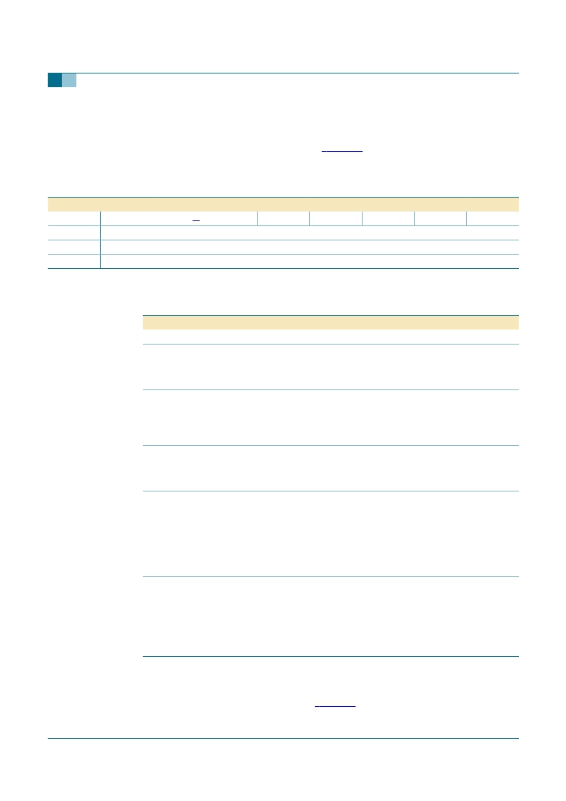
10.5.2
Control Function register (R/W: 0228h)
The Control Function register performs the buffer management on endpoints. It consists
of 1 B, and the bit configuration is given in
Table 108
. The register bits can stall, clear or
validate any enabled data endpoint. Before accessing this register, the Endpoint Index
register must be written first to specify the target endpoint.
[1]
The reserved bits should always be written with the reset value.
10.5.3
Data Port register (R/W: 0220h)
This 2 B register provides direct access for a microcontroller to the FIFO of the indexed
endpoint. The bit description is shown in
Table 110
.
Table 108: Control Function register: bit allocation
Bit
7
Symbol
Reset
0
Bus reset
0
Access
R/W
6
5
4
3
2
1
0
reserved
[1]
0
0
R/W
CLBUF
0
0
R/W
VENDP
0
0
R/W
DSEN
0
0
R/W
STATUS
0
0
R/W
STALL
0
0
R/W
0
0
R/W
Table 109: Control Function register: bit description
Bit
Symbol
Description
7 to 5 -
reserved
4
CLBUF
Clear Buffer:
Logic 1 clears the RX buffer of the indexed endpoint; the TX
buffer is not affected. The RX buffer is automatically cleared once the endpoint
is completely read. This bit is set only when it is necessary to forcefully clear
the buffer.
3
VENDP
Validate Endpoint:
Logic 1 validates the data in the TX FIFO of an IN endpoint
for sending on the next IN token. In general, the endpoint is automatically
validated when its FIFO byte count has reached the endpoint MaxPacketSize.
This bit is set only when it is necessary to validate the endpoint with the FIFO
byte count that is below the Endpoint MaxPacketSize.
2
DSEN
Data Stage Enable
: This bit controls the response of the ISP1761 to a control
transfer. When this bit is set, the ISP1761 goes to the data stage; otherwise, the
ISP1761 will NAK the data stage transfer until the firmware explicitly responds
to the setup command.
1
STATUS
Status Acknowledge:
Only applicable for control IN and OUT.
This bit controls the generation of ACK or NAK during the status stage of a
SETUP transfer. It is automatically cleared when the status stage is completed
and a SETUP token is received. No interrupt signal will be generated.
0 —
Sends NAK
1 —
Sends an empty packet following the IN token (host-to-peripheral) or ACK
following the OUT token (peripheral-to-host).
0
STALL
Stall Endpoint
: Logic 1 stalls the indexed endpoint. This bit is not applicable for
isochronous transfers.
Remark:
‘Stall’ing a data endpoint will confuse the Data Toggle bit regarding
the stalled endpoint because the internal logic starts from where it is stalled.
Therefore, the Data Toggle bit must be reset by disabling and re-enabling the
corresponding endpoint (by setting bit ENABLE to logic 0 or logic 1 in the
Endpoint Type register) to reset the PID.
相關PDF資料 |
PDF描述 |
|---|---|
| ISP1761BE | Hi-Speed Universal Serial Bus On-The-Go controller |
| ISP1761ET | Hi-Speed Universal Serial Bus On-The-Go controller |
| ISP2100A | Telecommunication IC |
| ISP2100BN4 | Microprocessor |
| ISP2300 | Controller Miscellaneous - Datasheet Reference |
相關代理商/技術參數 |
參數描述 |
|---|---|
| ISP1761BE | 功能描述:USB 接口集成電路 USB HS OTG CTRLR RoHS:否 制造商:Cypress Semiconductor 產品:USB 2.0 數據速率: 接口類型:SPI 工作電源電壓:3.15 V to 3.45 V 工作電源電流: 最大工作溫度:+ 85 C 安裝風格:SMD/SMT 封裝 / 箱體:WLCSP-20 |
| ISP1761BE,518 | 功能描述:USB 接口集成電路 USB HS OTG CONTROLLER RoHS:否 制造商:Cypress Semiconductor 產品:USB 2.0 數據速率: 接口類型:SPI 工作電源電壓:3.15 V to 3.45 V 工作電源電流: 最大工作溫度:+ 85 C 安裝風格:SMD/SMT 封裝 / 箱體:WLCSP-20 |
| ISP1761BE,551 | 功能描述:USB 接口集成電路 DO NOT USE ORDER -T OR NO "-" RoHS:否 制造商:Cypress Semiconductor 產品:USB 2.0 數據速率: 接口類型:SPI 工作電源電壓:3.15 V to 3.45 V 工作電源電流: 最大工作溫度:+ 85 C 安裝風格:SMD/SMT 封裝 / 箱體:WLCSP-20 |
| ISP1761BE,557 | 功能描述:USB 接口集成電路 USB HS OTG CTRLR RoHS:否 制造商:Cypress Semiconductor 產品:USB 2.0 數據速率: 接口類型:SPI 工作電源電壓:3.15 V to 3.45 V 工作電源電流: 最大工作溫度:+ 85 C 安裝風格:SMD/SMT 封裝 / 箱體:WLCSP-20 |
| ISP1761BE518 | 制造商:ST-Ericsson 功能描述:IC CONTROLLER USB OTG 128LQFP |
發布緊急采購,3分鐘左右您將得到回復。