- 您現在的位置:買賣IC網 > PDF目錄98215 > TFP6424PAP (TEXAS INSTRUMENTS INC) SPECIALTY CONSUMER CIRCUIT, PQFP64 PDF資料下載
參數資料
| 型號: | TFP6424PAP |
| 廠商: | TEXAS INSTRUMENTS INC |
| 元件分類: | 消費家電 |
| 英文描述: | SPECIALTY CONSUMER CIRCUIT, PQFP64 |
| 封裝: | 10 X 10 MM, 1.40 MM HEIGHT, 0.50 MM PITCH, THERMALLY ENHANCED, POWER, PLASTIC, TQFP-64 |
| 文件頁數: | 7/65頁 |
| 文件大小: | 813K |
| 代理商: | TFP6424PAP |
第1頁第2頁第3頁第4頁第5頁第6頁當前第7頁第8頁第9頁第10頁第11頁第12頁第13頁第14頁第15頁第16頁第17頁第18頁第19頁第20頁第21頁第22頁第23頁第24頁第25頁第26頁第27頁第28頁第29頁第30頁第31頁第32頁第33頁第34頁第35頁第36頁第37頁第38頁第39頁第40頁第41頁第42頁第43頁第44頁第45頁第46頁第47頁第48頁第49頁第50頁第51頁第52頁第53頁第54頁第55頁第56頁第57頁第58頁第59頁第60頁第61頁第62頁第63頁第64頁第65頁
TFP6422, TFP6424
PanelBus
DIGITAL TRANSMITTER/VIDEO ENCODER COMBO
SLDS118 – MARCH 2000
15
POST OFFICE BOX 655303
DALLAS, TEXAS 75265
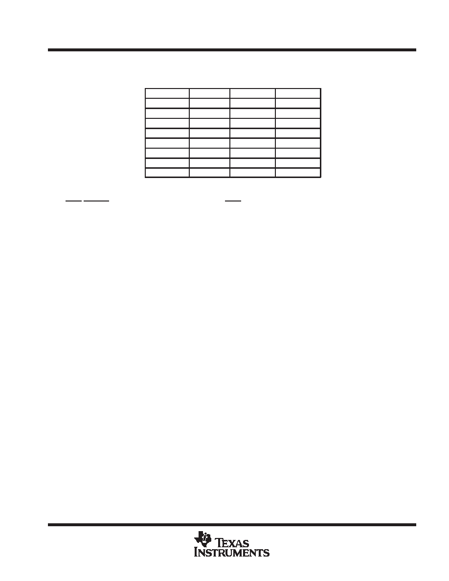
functional description (continued)
Table 1. 100/100 Color Bar Table in 2’s Complement
COLOR
Y (Hex)
Cr (Hex)
Cb (Hex)
White
6B
00
Yellow
52
12
90
Cyan
2A
90
26
Green
11
A2
B6
Magenta
EA
5E
4A
Red
D1
70
DA
Blue
A9
EE
70
Black
90
00
For diagnostic purposes, data manager can be forced to output 100/100 color bar YCbCr data by setting CBAR
bit to 1. CBAR bit can be set to 1 through I2C interface or can be defaulted to 1 after reset by pulling down
INT0/CBARE Pin (Pin 9). For normal operations, INT0 pin should be pulled up.
DVI encoder
The DVI encoder receives RGB pixel data from Data Manager and encodes the pixel data based on the T.M.D.S.
(Transition Minimized Differential Signaling) encoding algorithm. The DVI Encoder consists of three
independent identical channels, each of which is responsible for encoding one color component. The encoding
algorithm minimizes the signal transition while maintaining a good DC balance to reduce EMI. The encoded data
is then serially shifted to the DVI output drivers for transmission. The low–voltage swing differential output
further reduces EMI.
Each channel is encoded independently. Each channel receives 2 bits of control data and 8 bits of color
component data. Depending on the state of BLANK#, the DVI encoder either encodes control data or color
components. In either case, the data is encoded to 10–bit character and serially shifted out with the LSB
transmitted first. Blue channel (Channel 0) receives HSYNC and VSYNC as the control data and the blue color
component as the pixel data. If BLANK# is low, indicating valid blue component data is not transmitting, the
DVI encoder of the blue channel encodes the HSYNC and VSYNC signals based on Table TBD. If BLANK# is
high, indicating valid blue component data is transmitting, the DVI encoder encodes the blue component data
based on the table in Appendix A. The Green channel (Channel1) and Red channel (Channel 2) operate in a
way similar to Blue channel with the exception that the control bits are hardwired to ‘0’.
There are two possible encoded characters for each pixel data. The DVI encoder keeps tracks of the difference
between the number of ones and zeros that have been sent and selects the character that minimizes the
difference in order to maintain the best DC balance. Appendix A of this product datasheet contains a table
mapping of the 256 8–bit RGB pixel data to one of two possible 10 bit T.M.D.S. characters.
A serializer serializes the 10–bit character in each channel. An on–chip PLL locks to the CLKIN0 and CLKIN1
and generates the 10X clock to drive the serializer. The 10X clock is also sent to the T.M.D.S. drivers for output.
scaling processor
The Scaling Processor scales down the input image in both horizontal and vertical directions. In addition to
scaling, the Scaling Processor filters the image in the vertical direction and removes annoying flickers, which
are common when computer–generated graphics or text, especially static images, are displayed on the TV.
Scaling Processor uses a 5–tap adaptive filter for vertical scaling and filtering, whose coefficients are
dynamically adjusted on a line–by–line basis to maintain optimal performance.
To preserve maximum
horizontal details, Scaling Processor scales internal encoding clock to process horizontal scaling.
PRODUCT
PREVIEW
相關PDF資料 |
PDF描述 |
|---|---|
| TFP9431CPAP | SPECIALTY CONSUMER CIRCUIT, PQFP64 |
| TG355ENK-7916 | 8.15 MHz, LOW PASS FILTER |
| TH355BDI-4957 | 4.43 MHz, BAND PASS FILTER |
| TH355LDK-7915 | 8.15 MHz, LOW PASS FILTER |
| TH355LNK-4550 | 10 MHz, LOW PASS FILTER |
相關代理商/技術參數 |
參數描述 |
|---|---|
| TFP70N06 | 制造商:TAK_CHEONG 制造商全稱:Tak Cheong Electronics (Holdings) Co.,Ltd 功能描述:N-Channel Power MOSFET 70A, 60V, 0.014Ω |
| TFP730 | 制造商:TAK_CHEONG 制造商全稱:Tak Cheong Electronics (Holdings) Co.,Ltd 功能描述:N-Channel Power MOSFET 5.5A, 400V, 0.95Ω |
| TFP740 | 制造商:TAK_CHEONG 制造商全稱:Tak Cheong Electronics (Holdings) Co.,Ltd 功能描述:N-Channel Power MOSFET 10A, 400V, 0.55Ω |
| TFP7433PZP | 制造商:Texas Instruments 功能描述: |
| TFP7445PZP-6 | 制造商:Texas Instruments 功能描述: |
發布緊急采購,3分鐘左右您將得到回復。