- 您現(xiàn)在的位置:買賣IC網(wǎng) > PDF目錄360993 > ISD-SR3000 PDF資料下載
參數(shù)資料
| 型號: | ISD-SR3000 |
| 文件頁數(shù): | 12/120頁 |
| 文件大小: | 1293K |
| 代理商: | ISD-SR3000 |
第1頁第2頁第3頁第4頁第5頁第6頁第7頁第8頁第9頁第10頁第11頁當(dāng)前第12頁第13頁第14頁第15頁第16頁第17頁第18頁第19頁第20頁第21頁第22頁第23頁第24頁第25頁第26頁第27頁第28頁第29頁第30頁第31頁第32頁第33頁第34頁第35頁第36頁第37頁第38頁第39頁第40頁第41頁第42頁第43頁第44頁第45頁第46頁第47頁第48頁第49頁第50頁第51頁第52頁第53頁第54頁第55頁第56頁第57頁第58頁第59頁第60頁第61頁第62頁第63頁第64頁第65頁第66頁第67頁第68頁第69頁第70頁第71頁第72頁第73頁第74頁第75頁第76頁第77頁第78頁第79頁第80頁第81頁第82頁第83頁第84頁第85頁第86頁第87頁第88頁第89頁第90頁第91頁第92頁第93頁第94頁第95頁第96頁第97頁第98頁第99頁第100頁第101頁第102頁第103頁第104頁第105頁第106頁第107頁第108頁第109頁第110頁第111頁第112頁第113頁第114頁第115頁第116頁第117頁第118頁第119頁第120頁
1-7
1—HARDWARE
ISD-SR3000
ISD
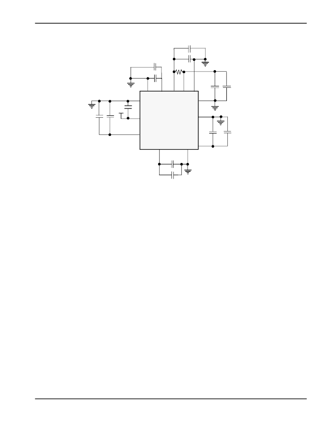
Figure 1-6:
1
5V Power Connection Diagram
For optimal noise immunity, the power and ground pins should be connected to V
CC
and the
ground planes, respectively, on the printed circuit board. If V
CC
and the ground planes are not
used, single conductors should be run directly from each V
CC
pin to a power point, and from
each GND pin to a ground point. Avoid daisy-chained connections. The ISD-SR3000 does not
perform recognition in power-down mode.
When you build a prototype, using wire-wrap or other methods, solder the capacitors directly to
the power pins of the ISD-SR3000 processor socket, or as close as possible, with very short
leads.
1.2.5
The ISD-SR3000 supports flash or ROM devices for storing voicetags, vocabulary, prompts,
and acoustic models, such that power can be removed from the system without any data loss.
The ISD-SR3000 supports AMD-compatible parallel flash devices, depending upon the re-
quired amount of memory. The recommended flash size is 16Mb, but larger sizes may be re-
quired for some applications. Organization can be 1Mb X 16 or 2Mb X 8. The recommended
device is Am29LV160D, which is organized as 1Mb X 16, and operates on a 3V power supply.
MEMORY INTERFACE
1.2.6
The ISD-SR3000 provides an on-chip interface for analog and digital telephony, supporting
master and slave CODEC interface modes. In master mode, the ISD-SR3000 controls the op-
eration of the CODEC for use in analog telephony or stand-alone applications. In the slave
mode, the ISD-SR3000 CODEC interface is controlled by an external source. This mode is
THE CODEC INTERFACE
97
95
87
86
85
76
66
64
17
19
20
40
42
V
SSA
C
1
V
SS
V
CC
V
CCHI
V
SS
V
CC
V
CC
V
SS
5 V Supply
ISD-SR3000
C
5
V
SS
V
CC
V
CCA
V
CC
V
SS
C
4
C
3
C
7
R
1
C
6
C
14
C
9
C
10
C
8
C
11
C
12
C
13
+
+
+
+
+
+
+
相關(guān)PDF資料 |
PDF描述 |
|---|---|
| ISD1100SERIES | ISD1110/ISD1112 Part2 |
| ISD1200SERIES | ISD1210/ISD1212 Part3 |
| ISD1400_1 | |
| ISD1400_2 | |
| ISD1400_3 | |
相關(guān)代理商/技術(shù)參數(shù) |
參數(shù)描述 |
|---|---|
| ISD-T266SA/J | 制造商:未知廠家 制造商全稱:未知廠家 功能描述:Solid-State Recorder |
| ISD-T266SA/Q | 制造商:未知廠家 制造商全稱:未知廠家 功能描述:Solid-State Recorder |
| ISD-T266SC/J | 制造商:未知廠家 制造商全稱:未知廠家 功能描述:Solid-State Recorder |
| ISD-T266SC/Q | 制造商:未知廠家 制造商全稱:未知廠家 功能描述:Solid-State Recorder |
| ISD-T266SP/J | 制造商:未知廠家 制造商全稱:未知廠家 功能描述:Solid-State Recorder |
發(fā)布緊急采購,3分鐘左右您將得到回復(fù)。