- 您現(xiàn)在的位置:買賣IC網(wǎng) > Datasheet目錄45 > NCT7491RQR2G (ON Semiconductor)IC REMOTE THERMAL MONITOR 24QSOP Datasheet資料下載
參數(shù)資料
| 型號(hào): | NCT7491RQR2G |
| 廠商: | ON Semiconductor |
| 文件頁數(shù): | 36/80頁 |
| 文件大小: | 844K |
| 描述: | IC REMOTE THERMAL MONITOR 24QSOP |
| 標(biāo)準(zhǔn)包裝: | 2,500 |
| 系列: | * |
第1頁第2頁第3頁第4頁第5頁第6頁第7頁第8頁第9頁第10頁第11頁第12頁第13頁第14頁第15頁第16頁第17頁第18頁第19頁第20頁第21頁第22頁第23頁第24頁第25頁第26頁第27頁第28頁第29頁第30頁第31頁第32頁第33頁第34頁第35頁當(dāng)前第36頁第37頁第38頁第39頁第40頁第41頁第42頁第43頁第44頁第45頁第46頁第47頁第48頁第49頁第50頁第51頁第52頁第53頁第54頁第55頁第56頁第57頁第58頁第59頁第60頁第61頁第62頁第63頁第64頁第65頁第66頁第67頁第68頁第69頁第70頁第71頁第72頁第73頁第74頁第75頁第76頁第77頁第78頁第79頁第80頁
NCT7491
http://onsemi.com
36
Voltage Measurement Selection
The user can select which voltage channels to include in
the monitoring loop. By only including the channels that are
required the loop monitoring time can be reduced.
" Setting <2> of register 0x11 includes the V
TT
channel
in the monitoring loop.
" Setting <3> of register 0x13 includes the 12V channel
in the monitoring loop.
" Setting <4> of register 0x13 includes the 5 V channel in
the monitoring loop.
" Setting <5> of register 0x13 includes the Vccp channel
in the monitoring loop.
" Setting <6> of register 0x13 includes the 2.5 V channel
in the monitoring loop.
" Setting <7> of register 0x13 includes the Vcc channel
in the monitoring loop.
Voltage Measurement Resolution
The NCT7491 uses a reference voltage of 2 V. The ADC
is 10bit giving a resolution of 1.953 mV per lsb. This is the
resolution that applies when the attenuators are disabled.
With attenuators enabled the resolution for each channel is
as follows:
" 12 V resolution = 15.92 mV per lsb
" 5 V resolution = 6.54 mV per lsb
" 2.5 V resolution = 3.26 mV per lsb
" Vccp resolution = 2.93 mV per lsb
" Vcc resolution = 4.29 mV per lsb
" V
TT
resolution = 2.2 mV per lsb
Voltage Limit Registers
Associated with each voltage measurement channel is a
high and low limit register. Exceeding the programmed high
or low limit causes the appropriate status bit to be set.
Exceeding either limit can also generate SMBALERT
interrupts.
" Reg. 0x84, V
TT
Low Limit
" Reg. 0x86, V
TT
High Limit
" Reg. 0x44, 2.5 V Low Limit
" Reg. 0x45, 2.5 V High Limit
" Reg. 0x46, V
CCP
Low Limit
" Reg. 0x47, V
CCP
High Limit
" Reg. 0x48, V
CC
Low Limit
" Reg. 0x49, V
CC
High Limit
" Reg. 0x4A, 5 V Low Limit
" Reg. 0x4B, 5 V High Limit
" Reg. 0x4C, 12 V Low Limit
" Reg. 0x4D, 12 V High Limit
Additional ADC Functions for Voltage Measurements
A number of other functions are available on the
NCT7491 to offer the system designer increased flexibility.
The functions described below are enabled by setting the
appropriate bit in configuration register 2 (0x73).
TurnOff Voltage Averaging
The averager length that is applied to the temperature
readings is also applied to the voltage readings. The averager
length is programmable as 4, 8, 16 or 32 samples. These
values can be selected in register 0x40 bits <7:6>.
When faster conversions are needed, setting Bit 3 of
Configuration Register 2 (Reg. 0x73) turns voltage
averaging off. This gives a faster reading, but the reading
can be noisier. The default roundrobin cycle time takes
TBD ms.
Bypass Individual Voltage Input Attenuators
Bits <7:3> of Configuration Register 4 (0x7D) can be
used to bypass individual voltage channel attenuators.
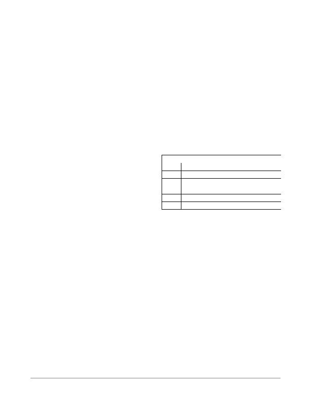
Table 30. BYPASSING VOLTAGE ATTENUATORS
Configuration Register 4 (0x7D)
Bit
Channel Attenuated
3
Bypass V
TT
attenuator
4
Bypass 2.5 V attenuator
5
Bypass V
CCP
attenuator
6
Bypass 5 V attenuator
7
Bypass 12 V attenuator
The input range of the ADC without the attenuators is 0 V
to 2 V.
GPIO Functions
There are up to 3 pins that can be configured as opendrain
general purpose digital I/O pins. These are pins 5 (GPIO1),
6 (GPIO2) and 19 (GPIO3) on the QSOP package and pins
2 (GPIO1), 3 (GPIO2) and 16 (GPIO3) on the QFN package.
GPIO1 and GPIO2 are shared with the SMBus Master Port
pins SCL_M and SDA_M. GPIO3 is shared with THERM
and SMBALERT functions.
There are 2 bits that must be programmed to enable the
GPIO1 and GPIO2 functions:
" Setting bit 1 of register 0x80 to 1 enables GPIO1 and
GPIO2
" Clearing bit 0 of register 0xB5 to 0 disables the SMBus
Master Port. This bit has priority over the GPIO enable
bit so must be cleared for GPIOs to function.
GPIO3 is enabled by setting bits <3:2> of register 0x7C to
<10>.
Each GPIO pin has associated direction, polarity and data
bits.
相關(guān)PDF資料 |
PDF描述 |
|---|---|
| NCT75MNR2G | IC SENSOR TEMP DGTL 8DFN |
| NCV8881PWR2G | IC REG TRPL BUCK/LINEAR 16SOIC |
| NE1617ADS,112 | IC TEMP MONITOR 16SSOP |
| NE1619DS,118 | IC TEMP MONITOR 16SSOP |
| NIS5112D1R2G | IC ELECTRONIC FUSE HOTSWAP 8SOIC |
相關(guān)代理商/技術(shù)參數(shù) |
參數(shù)描述 |
|---|---|
| NCT75DMR2G | 功能描述:板上安裝溫度傳感器 2-Channel Digital Thermometer w/ Alarm RoHS:否 制造商:Omron Electronics 輸出類型:Digital 配置: 準(zhǔn)確性:+/- 1.5 C, +/- 3 C 溫度閾值: 數(shù)字輸出 - 總線接口:2-Wire, I2C, SMBus 電源電壓-最大:5.5 V 電源電壓-最小:4.5 V 最大工作溫度:+ 50 C 最小工作溫度:0 C 關(guān)閉: 安裝風(fēng)格: 封裝 / 箱體: 設(shè)備功能:Temperature and Humidity Sensor |
| NCT75DR2G | 功能描述:板上安裝溫度傳感器 2-Channel Digital Thermometer w/ Alarm RoHS:否 制造商:Omron Electronics 輸出類型:Digital 配置: 準(zhǔn)確性:+/- 1.5 C, +/- 3 C 溫度閾值: 數(shù)字輸出 - 總線接口:2-Wire, I2C, SMBus 電源電壓-最大:5.5 V 電源電壓-最小:4.5 V 最大工作溫度:+ 50 C 最小工作溫度:0 C 關(guān)閉: 安裝風(fēng)格: 封裝 / 箱體: 設(shè)備功能:Temperature and Humidity Sensor |
| NCT75MNR2G | 功能描述:板上安裝溫度傳感器 HAS2MONOJLCC84SPACE RoHS:否 制造商:Omron Electronics 輸出類型:Digital 配置: 準(zhǔn)確性:+/- 1.5 C, +/- 3 C 溫度閾值: 數(shù)字輸出 - 總線接口:2-Wire, I2C, SMBus 電源電壓-最大:5.5 V 電源電壓-最小:4.5 V 最大工作溫度:+ 50 C 最小工作溫度:0 C 關(guān)閉: 安裝風(fēng)格: 封裝 / 箱體: 設(shè)備功能:Temperature and Humidity Sensor |
| NCT7717U TR | 制造商:Nuvoton Technology Corp 功能描述:SMBUS INTERFACE TEMP. SENSOR W 制造商:Nuvoton Technology Corp 功能描述:IC SMBUS TEMP SENSOR 8MSOP |
| NCT7718W TR | 制造商:Nuvoton Technology Corp 功能描述:IC SMBUS TEMP SENSOR 8MSOP |
發(fā)布緊急采購,3分鐘左右您將得到回復(fù)。